4.1Protection From Mechanical Damage Using Geokon Model 4000-6
Special cover plates made from sheet steel formed into a channel shape are available from geokon. Use the mounting hardware provided to install the cover plates as follows:
1.Weld the two 9.5 x 51 mm (3/8 x 2") long hex bolts in place head down. The bolts should be spaced at a nominal 530 mm (21") apart. A spacer jig is available from geokon, or the cover plate can be flipped onto its back and the holes in the cover plate can be used to mark the bolt locations. One hole in the cover plate is slotted so that the spacing is not critical. Avoid welding near the gauge as this will cause large local distortions of the metal. Use a special stud welder or an arc welder to weld the head of the bolt to the surface.
2.Place the cover plate over the welded bolts.
3.Install washers, then nuts. Avoid using excessive force while tightening the cover retaining nuts as this will distort the underlying steel surface and can give rise to spurious strain readings. The two figures below show the completed installation.
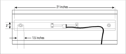
Figure 7: Cover Plate Installation, Top View
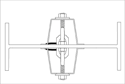
Figure 8: Cover Plate Installation, Side View
4.2Protection From Direct Sunlight and Rapid Changes in Ambient Temperature
The thermal coefficient of expansion of the steel vibrating wire inside the gauge is the same as that for the steel of the structure to which the gauge is attached; therefore, no temperature correction to the measured strain is required when calculating load induced strains. However, this is only true if the wire and the underlying steel structure are at the same temperature. If sunlight is allowed to impinge directly onto the gauge, it could elevate the temperature of the wire above the surrounding steel and cause large changes in apparent strain. Therefore, always shield strain gauges from direct sunlight. Protection from temperature changes is best provided by covering the gauges with a layer of insulating material such as Polystyrene foam or fiberglass.
4.3Cable and Connector Protection
The cable should be protected from accidental damage caused by moving equipment or fly rock. This is best accomplished by putting the cable inside flexible conduit and positioning the conduit in as safe a place as possible. (Flexible conduit is available from geokon.) The conduit can be connected via conduit bulkhead connectors to the cover plates and then to a readout. (The geokon cover plate has a stamped knockout which, when removed, provides a hole for connecting the conduit connector.)
4.4Cable Splicing and Termination
Terminal boxes with sealed cable entries are available from geokon for all types of applications. These allow many gauges to be terminated at one location with complete protection of the lead wires. The interior panel of the terminal box can have built-in jacks or a single connection with a rotary position selector switch. Contact geokon for specific application information.
Because the vibrating wire output signal is a frequency rather than a current or voltage, variations in cable resistance have little effect on gauge readings; therefore, splicing of cables has no ill effects, and in some cases may in fact be beneficial. The cable used for making splices should be a high quality twisted pair type, with 100% shielding and an integral shield drain wire. When splicing, it is very important that the shield drain wires be spliced together. Always maintain polarity by connecting color to color.
Splice kits recommended by geokon incorporate casts that are placed around the splice and are then filled with epoxy to waterproof the connections. When properly made, this type of splice is equal or superior to the cable in strength and electrical properties. Contact geokon for splicing materials and additional cable splicing instructions.
You can terminate a cable by stripping and tinning the individual conductors and then connecting them to the patch cord of a readout box. Alternatively, you can use a connector to plug directly into the readout box or to a receptacle on a special patch cord.
You can inhibit corrosion by applying a coat of rust preventative paint at the weld points.
Unlike numerous other types of instrumentation available from geokon, vibrating wire strain gauges do not have any integral lightning protection components, such as transorbs or plasma surge arrestors.
Suggested Lightning Protection Options:
n Lighting arrestor boards and enclosures are available from geokon. These units install where the instrument cable exits the structure being monitored. The enclosure has a removable top to allow the customer to service the components or replace the board in the event that the unit is damaged by a lightning strike. A connection is made between the enclosure and earth ground to facilitate the passing of transients away from the gauge. See the figure below.
n Plasma surge arrestors can be epoxied into the instrument cable, close to the sensor. A ground strap then connects the surge arrestor to an earth ground, such as a grounding stake or the steel structure.
Consult the factory for additional information on available lightning protection.
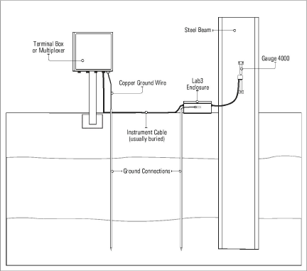
Figure 9: Lightning Protection Scheme