7.Data Reduction
Readings in position C on geokon’s readout boxes are displayed directly in microstrain based on the theoretical equation:
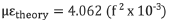
equation 5: Theoretical Microstrain
Where µε is the strain in the wire in microstrain and f is the resonant frequency of the vibrating wire.
7.1Conversion of the Readings to Strain Changes
In practice, the method of wire clamping effectively shortens the vibrating wire slightly, causing it to over-register the strain. This effect is removed by applying the batch gauge factor (B) from the calibration report supplied with the gauges.
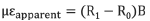
equation 6: Strain Calculation
Where R0 is the initial reading on position C and R1 is a subsequent reading.
Note: When (R1 - R0) is positive, the strain is tensile.
The value obtained from the above equation is required for computing stresses in equations steps two through four in Appendix B. The stresses thus computed are the total of those caused by both construction activity and by any temperature change that may have occurred.
7.2Converting Strains to Stresses
Strain gauges measure strain or deformation of the structure, however, the designer is usually more interested in the structural loads or stresses. This requires a conversion from the measured strains to computed stresses.
Strain changes are computed from strain gauge readings taken at various times, and by comparison with some initial readings taken at time zero. This initial reading is best taken when the structural member is under no load, i.e., the gauges should be mounted while the member is still in the steel yard or warehouse.
This is not always possible and often strain gauges are installed on members that are under some existing load so that subsequent strain changes will always begin from some unknown datum. However, a technique exists, namely the “Blind Hole Drilling Method” (Photolastic 1977), whereby residual or existing stresses can be measured. The procedure is to cement a strain gauge rosette to the surface and then analyze the strains caused by drilling a short blind hole in the center of the rosette. However, it is a well-known fact that strains can be locked into the steel during its manufacture. (Often, the skin of a rolled steel structural member is under tension relative to the underlying steel.)
Sometimes it is possible, especially where temporary supports are being monitored, to measure the strain in the structural member after the structure has been dismantled. This “no load” reading should agree with the initial “no load” reading. Any lack of agreement would be an indication of gauge zero drift, although the possibility of some permanent plastic deformation of the member should not be overlooked, particularly where measured strains were high enough to approach the yield point.