4.Installing the Gauges in Concrete
geokon strain gauges are typically set into concrete in one of two ways:
1.Cast the units directly into the concrete mix (see Sections 4.1 through 4.3)
2.Cast them into briquettes that are subsequently cast into the concrete structure (see Section 4.4).
When casting the gauge directly into the concrete mix, take care to avoid applying any large forces to the end blocks during installation. This is most imperative when installing Model 4202 gauges.
Model 4202 Note: Do not wrap an iron tie wire around the body of the gauge; doing so could cause damage due to its delicate construction. Instead, use the holes in the end blocks to affix the gauge to the rebar, being sure that the gauge is not tensioned or compressed in the longitudinal direction.
Model 4200L Note: This gauge is specifically designed to allow strains to be measured in curing concrete. However, do not bury the gauge more than one meter deep; doing so could damage the gauge.
1.Place two pieces of wood or polystyrene foam between the gauge and the rebar as shown in Figure 10 below.
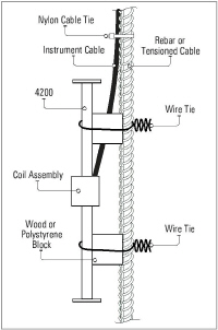
Figure 10: Attaching Gauges to Rebar
2.Use soft iron tie wire, similar to the kind that is normally used for tying rebar cages together. Run the wire around the body of the strain gauge and around the rebar. Twist the wire around itself to hold the gauge in place.
3.Tie the instrument cable off to the rebar using nylon cable ties.
Note: Don’t tie the wires too tightly, since rebar and tension cables tend to move during concrete placement and vibration. Take care not to damage the cable with the vibrator. The gauge can also be placed directly into the mix if it can be assured that the orientation will be correct after the gauge placement.
1.Wrap a layer of self-vulcanizing rubber tape 3 cm from each gauge end, as shown in Figure 11.
Model 4210 Note: This step is not necessary
The layers of rubber serve as a shock absorber, dampening any vibration of the suspension system. Without the rubber layers, the resonant frequency of the tie wires might interfere with the resonant frequency of the gauge when the tie wires are tightened. This can result in unstable readings, or in no readings at all. However, this problem disappears once the concrete has been placed.
For a method that avoids this potential problem, see Section 4.3.
2.Use soft iron tie wire, the kind normally used for tying rebar cages together. Wrap the wire around the rubber strips twice.
3.Twist two loops in the wire, one on either side of the gauge, at a distance of 3 cm from the gauge body. Repeat this process at the other end.
4.Position the gauge between the rebar and twist the wire ends twice around the rebar, then around itself.
5.Tighten the wire and orient the gauge by twisting the loops between the gauge and the rebar.
6.Attach the plucking coil using a hose clamp. Tie the instrument cable off to one of the rebar using nylon cable ties.
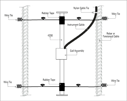
Figure 11: Suspending Model 4200/4200L/4200HT Strain Gauges Between Rebar
4.3Alternative Suspension Method
Tie two short pieces of steel rebar to the existing rebar using nylon cable ties, as shown in the figure below. Then tie the strain gauge to the short pieces of rebar again using more nylon cable ties. This method avoids the resonance problems associated with the previous method.
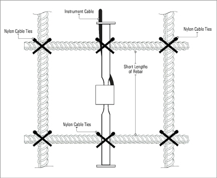
Figure 12: Alternative Method for Attaching Model 4200/4200HT Strain Gauges to Rebar
4.4Using Pre-cast Briquettes, Shotcrete, or Grouting
An alternative to casting the units into the concrete mix directly is to precast the gauges into briquettes of the same mix as the mass concrete and then place the briquettes in the structure prior to concrete placement. The briquettes should be constructed no more than three days prior to installation, but no less than one day prior, and should be continuously cured with water while awaiting placement in the mass concrete.
geokon strain gauges may also be used in shotcrete, as well as in holes drilled in rock or concrete that are subsequently grouted. When used in shotcrete, special care should be taken to protect the lead wires, such as encasing them in conduit or heavy tubing. The gauges may be placed by packing the immediate area around the gauge by hand and then proceeding with the shotcrete operation.
4.5Cable Splicing and Termination
The cable from the strain gauges can be protected by using flexible conduit, which can be supplied by GEOKON.
Terminal boxes with sealed cable entries are available from geokon for all types of applications. These allow many gauges to be terminated at one location with complete protection of the lead wires. The interior panel of the terminal box can have built-in jacks or a single connection with a rotary position selector switch. Contact geokon for specific application information.
Because the vibrating wire output signal is a frequency rather than a current or voltage, variations in cable resistance have little effect on gauge readings; therefore, splicing of cables has no ill effects, and in some cases may be beneficial. The cable used for making splices should be a high-quality twisted pair type, with 100% shielding and an integrated shield drain wire. When splicing, it is very important that the shield drain wires be spliced together. Always maintain polarity by connecting color to color.
Splice kits recommended by geokon incorporate casts, which are placed around the splice and are then filled with epoxy to waterproof the connections. When properly made, this type of splice is equal or superior to the cable itself in strength and electrical properties. Contact geokon for splicing materials and additional cable splicing instructions.
Cables may be terminated by stripping and tinning the individual conductors and then connecting them to the patch cord of a readout box. Alternatively, a connector may be used which will plug directly into the readout box or to a receptacle on a special patch cord.
Unlike numerous other types of instrumentation available from geokon, embedment strain gauges do not have any integrated lightning protection components, such as transorbs or plasma surge arrestors. Usually this is not a problem, as these types of gauges are installed within concrete or grout and are somewhat isolated from potentially damaging electrical transients. However, there may be occasions where some sort of lightning protection is desirable. One such example is where the gauge is in contact with rebar that may be exposed to direct or indirect lightning strikes. In addition, if the instrument cable is exposed, it may be appropriate to install lightning protection components, as the transient could travel down the cable to the gauge and possibly destroy it.
Suggested Lightning Protection Options
nLighting arrestor boards and enclosures are also available from geokon. These units install where the instrument cable exits the structure being monitored. The enclosure has a removable top to allow the customer to service the components or replace the board in the event that the unit is damaged by a lightning strike. A connection is made between the enclosure and earth ground to facilitate the passing of transients away from the gauge. See the figure below.
nPlasma surge arrestors can be epoxied into the instrument cable, close to the sensor. A ground strap then connects the surge arrestor to an earth ground, such as a grounding stake or the rebar itself.
Consult the factory for additional information on available lightning protection.
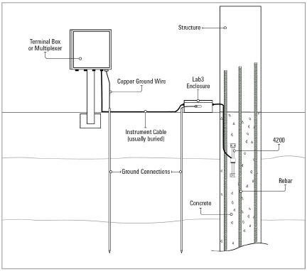
Figure 13: Lightning Protection Scheme