Appendix B.Theory of Operation
A vibrating wire attached to the surface of a deforming body will deform in a manner similar to that of the deforming body. These deformations alter the tension of the wire, which alters its natural frequency of vibration (resonance).
The examples below are calculated using the Model 4200 gauge parameters. Substitute the values from the table below for Models 4202 and 4204.
Note: These equations do not apply to Models 4210, 4212, and 4214.
|
Model: |
4200/4200HT/4200HT‑T |
4202 |
4204 |
|
Gauge Length (Lg): |
6 inches |
2 inches |
4 inches |
|
Wire Length (Lw): |
5.875 inches |
2 inches |
3.875 inches |
|
Gauge Factor: |
3.304 |
0.391 |
1.422 |
table 5: Embedment Strain Gauge Theoretical Parameters
The relationship between frequency (period) and deformation (strain) is described as follows:
1.The fundamental frequency (resonant frequency) of vibration of a wire is related to its tension, length, and mass. The fundamental frequency may be determined by the equation:

Where:
Lw is the length of the wire in inches.
F is the wire tension in pounds.
m is the mass of the wire per unit length (pounds, seconds2/inches2).
2.Note that:

Where:
W is the weight of Lw inches of wire in pounds.
g is the acceleration of gravity (386 inches/seconds2).
3.And:

Where:
ρ is the wire material density (0.283 pounds/inches3).
a is the cross-sectional area of the wire in inches2.
4.Combining the equations from steps one, two, and three gives:

5.Note that the tension (F) can be expressed in terms of strain, e.g.,

Where:
Ɛw is the wire strain (inches/inches).
E is the Young's Modulus of the wire (30 x 106 Psi).
6.Combining the equations from steps four and five gives:

7.Substituting the given values for E, g, and ρ yields:
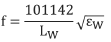
8.In position A, (which displays the period of vibration, T) multiplied by a factor of 106:

9.Combining the equations from steps seven and eight gives:

10.The equation from step nine must now be expressed in terms of the strain in the surface of the body to which the gauge is attached. Since the deformation of the body must equal the deformation of the wire:

Where:
Ɛ is the strain in the body.
Lg is the gauge length in inches.
11.Combining the equations from steps nine and ten gives:
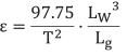
Where: (for Model 4200)
Lw is 5.875 inches.
Lg is 6.000 inches.
12.Therefore:
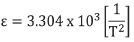
13.The display on position 'D' of the readout is based on the equation:
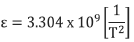
The squaring, inverting, and multiplication by the factor 3.304 x 10⁹ is all done internally by the microprocessor of the readout so that the displayed reading in position D is given in microinches per inch (ε).
Note: In the previous steps, T is seconds x 106 and ε is microinches per inch.
An alternative is: ε = 3.304 x 10⁻³ f2 microstrain.
Where f is the frequency in Hz.