1.Theory Of Operation
geokon vibrating wire stressmeters are designed primarily for long-term measurements of stress changes in rock, by utilizing a vibrating wire transducer to measure the deformation of a thick-walled steel ring preloaded into a borehole by a wedge and platen assembly as shown in the figure below.
1:
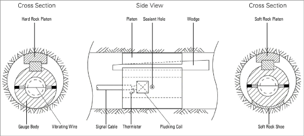
Figure 1: Vibrating Wire Stressmeter
In use, changing rock stresses impose changing loads on the gauge body causing the body to deflect, and this deflection is noted as a change in tension and resonant frequency of vibration of the vibrating wire element. The square of the vibration frequency is directly proportional to the change in diameter of the gauge and, by calibration, to the change in stress in the rock.
The actual calibration of the gauge depends upon many factors including the host rock elastic constants, the prestress applied during installation, the orientation of the stressmeter with respect to the principal rock stress direction and platen contact area. Thus, the accuracy of the gauge reading is largely indeterminate, and the indicated stress magnitude can only be approximate.
A coil and magnet assembly located close to the wire is used to both excite the wire and sense the resultant frequency of vibration. When the gauge is connected, a pulse of varying frequency is applied to the coil and magnet assembly, and this causes the wire to vibrate at its resonant frequency. The wire continues to vibrate, and a signal, at the gauge frequency, is induced in the pickup coil and transmitted to the readout box where it is conditioned and displayed.
In theory, where the effective modulus of the stressmeter (approximately 28 GPa (4 x 10⁶ PSI)) is more than two times the modulus of the host rock, conversion of the readings to changes in stress does not require an accurate knowledge of the rock modulus, and this is the reason for using the term stressmeter for this device. However, in most rocks, and especially in harder rocks, the modulus must be known to improve the accuracy of the stress measurements, and calibration curves provided herein give sensitivity factors for materials of different moduli. It should be noted that as the rock modulus changes by a factor of 10, the gauge factor changes only by a factor of two.
The stressmeter is a uniaxial device. To completely evaluate stress changes in a given plane, three stressmeters, installed at 0°, 45°, and 90° orientations, are required.
The gauge wire in the Model 4300 Series stressmeters runs perpendicular to the direction in which the gauge body is loaded in an effort to minimize the effects of point loading, off center loading, etc. This gives the gauge a very high range and, since as the load increases the wire gets tighter, the wire never goes slack.
Gauge installation is accomplished by driving a wedge between the gauge body and the platen, which contacts the borehole walls. Preloading to desired levels is accomplished by further driving of the wedge with the setting tool. In soft rocks, a soft rock platen and soft rock shoe are used to increase the area of contact.
The gauge is constructed of corrosion resistant materials and should have an indefinite lifetime under even the most severe conditions.