4.Data Reduction
4.1Change in Stress Calculation
To obtain the change in stress at any given time the following equation applies:
σ = (R1 − R0) G
equation 1: Change in Stress
Where;
σ = Stress change in psi.
R0 = Initial reading after the gauge has been set in place.
R1 = Reading at subsequent stress.
Table 1 gives example calculations for the various models.
|
Model |
EX |
BX |
NX |
|
Readout initial display (R0)= |
10,000 |
4,000 |
2,500 |
|
Subsequent display (R1)= |
12,000 |
5,000 |
3,000 |
|
Values entered into the equation above |
σ = (12,000 − 10,000) 0.50 |
σ = (5,000 − 4,000) 2.5 |
σ = (3,000 − 2,500) 6.0 |
|
Change in Stress = |
σ = 1,000 psi |
σ = 2500 psi |
σ = 3,000 psi |
table 1: Sample Calculations
Positions F and B are used for stressmeters, the processor converts the period readings to units of frequency squared, which is proportional to wire strain, gauge deflection and applied stress. A reading of 10,000 on channel F corresponds to a period of 316.2 microseconds on channel A.
Since the purpose of the stressmeter installation is to monitor site conditions, factors that may affect these conditions should always be observed and recorded. Seemingly minor effects may have a real influence on the behavior of the structure being monitored and may give an early indication of potential problems. Some of these factors include, but are not limited to, blasting, rainfall, tidal levels, excavation and fill levels and sequences, traffic, temperature and barometric changes, changes in personnel, nearby construction activities, seasonal changes, etc.
The graphs in Figure 7, Figure 8, and Figure 9 are used to determine the stress sensitivity or gauge factor for rocks of different moduli. Sensitivity factors are based on experimental data conducted on rock samples and can only serve as a guide. For more accurate determinations of stress sensitivity, calibrations must be performed in samples of the rock being monitored.
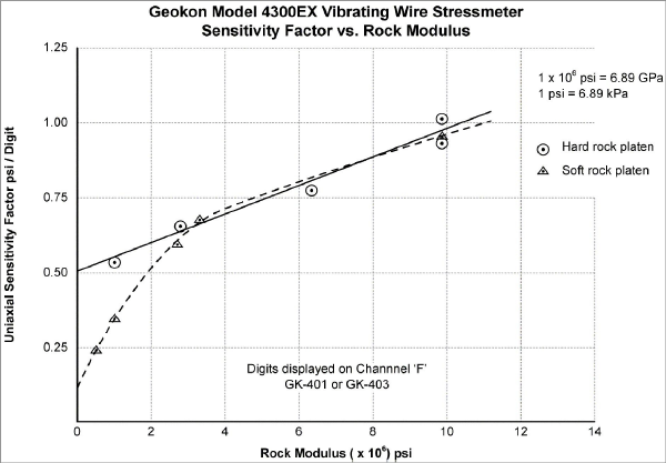
Figure 7: Model 4300EX Sensitivity Factor vs. Rock Modulus
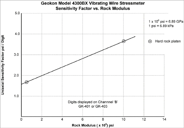
Figure 8: Model 4300BX Sensitivity Factor vs. Rock Modulus
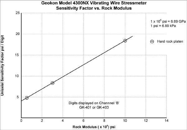
Figure 9: Model 4300NX Sensitivity Factor vs. Rock Modulus
4.4Corrections for Temperature Changes
The materials used in the construction of the stressmeter are affected by changes in ambient temperature. Since these gauges are normally installed underground in constant temperature environments, corrections are not normally applied. However, if maximum accuracy is desired, or the temperature changes are extreme, a correction may be applied.
The temperature correction factor for the gauge reading on a readout box is two digits/°C, indicating an apparent decrease in rock stress for a temperature rise. Stress correction for temperature is given by the equation:
σT = (R1 − R0) G + (T1 − T0) 2G
equation 2: Temperature Correction
Where;
σT = The stress change corrected for temperature.
R0 = Initial reading after the gauge has been set in place.
R1 = Reading at subsequent stress.
T0 = Initial temperature °C
T1 = Subsequent temperature °C
G = Sensitivity factor taken from Section 4.3.
It should be noted that this temperature correction factor is for a gauge in a free field with no restraints. In a field condition where the gauge is firmly placed in a borehole the gauge temperature sensitivity is also dependent on the gauge/rock interactions, and these relationships are very complex and beyond the scope of this manual. Calibration would be required for accurate determination of the thermal characteristics of the gauge.