3.Instrument Protection
3.1Cable Splicing and Termination
Terminal boxes with sealed cable entries are available from geokon for all types of applications. These allow many instruments to be terminated at one location with complete protection of the lead wires. The interior panel of the terminal box can have built-in jacks or a single connection with a rotary position selector switch. Contact geokon for specific application information.
Because the vibrating wire output signal is a frequency rather than a current or voltage, variations in cable resistance have little effect on instrument readings; therefore, splicing of cables has no ill effects, and in some cases may in fact be beneficial. The cable used for making splices should be a high quality twisted pair type, with 100% shielding and an integral shield drain wire. When splicing, it is very important that the shield drain wires be spliced together. Always maintain polarity by connecting color to color.
Splice kits recommended by geokon incorporate casts that are placed around the splice and are then filled with epoxy to waterproof the connections. When properly made, this type of splice is equal or superior to the cable in strength and electrical properties. Contact geokon for splicing materials and additional cable splicing instructions.
Terminate a cable by stripping and tinning the individual conductors and then connecting them to the patch cord of a readout box. Alternatively, use a connector to plug directly into the readout box or to a receptacle on a special patch cord.
3.2Protection from Mechanical Damage
It is important that you protect the crackmeter from damage. geokon makes steel cover plates, Model 4420-7, for this purpose. geokon makes them using sheet steel formed into a channel shape. The standard cover plate is long enough to cover the two-inch range crackmeter; longer range crackmeters use multiple cover plates tack-welded together.
7:
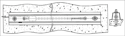
Figure 7: Typical Cover Plate Installation
The mounting nut and washer should be tightened only loosely to enable the cover to slide on the 3/8 threaded rods. An extra nut is provided as a locknut. Critical dimensions of the extended range covers are shown in the table below.
|
Range |
Total Length |
Hole Spacing |
Slot Lengths |
|
100 mm (4") |
36" |
32.5" |
2" |
|
150 mm (6") |
36" |
31.5" |
3" |
|
200 mm (8") |
48" |
42.5" |
4" |
|
300 mm (12") |
60" |
52.5" |
6" |
table 3: Dimensions of Extended Range Covers
3.3Cable and Connector Protection
The cable should be protected from accidental damage caused by moving equipment or fly rock. This is best accomplished by putting the cable inside flexible conduit and positioning the conduit in as safe a place as possible. (Flexible conduit is available from geokon.) The conduit can be connected via conduit bulkhead connectors to the cover plates. (The geokon cover plate has a stamped knockout which, when removed, provides a hole for connecting the conduit connector.)
It is imperative that installation weld points, if any, be protected from corrosion. Stainless steel instruments will not corrode, but the substrate can corrode, especially at weld points, unless they are covered by a waterproofing layer. geokon recommends you follow this procedure:
1.Apply several drops of cyanoacrylate adhesive to the edge of all spot welded mounting tabs. The glue will wick into the gap between the mounting tabs and the substrate and provide the first line of defense.
2.Mask off the areas where spot welds are needed.
3.Spray a coat of self-etching primer (available at any auto parts store) over mounting tab areas and all exposed bare metal areas. The idea is to protect substrate weld points. It is important to completely cover mounting tab edges, paying particular attention to the point where the tab is under the instrument. Be sure to spray beneath the coil housing, if applicable; do not worry if the primer also coats the instrument.
4.Apply a coat of paint over the primed areas.
3.5Protection From Electrical Noise
Be sure to install instrument cables as far away as possible from sources of electrical interference such as power lines, generators, motors, transformers, arc welders, etc. Cables should never be buried or run with AC power lines. Doing so will cause the instrument cables to pick up the frequency noise from the power cable, and this will likely make obtaining a stable reading difficult.
3.6Protection From Sunlight and Temperature Changes
If attached to a steel structure, the thermal coefficient of expansion of the steel vibrating wire inside the instrument is the same as that for the structure. This means that no temperature correction for the measured strain is required when calculating load-induced strains. However, this is only true if the wire and the underlying steel structure are at the same temperature. If sunlight is allowed to impinge directly onto the gauge, it could elevate the temperature of the wire above the surrounding steel and cause large changes in apparent strain. Therefore, always shield strain gauges from direct sunlight. Protection from thermal effects is best provided by covering the gauges with a layer of insulating material such as Polystyrene foam or fiberglass.
Unlike numerous other types of instrumentation available from geokon, vibrating wire strain instruments do not have any integral lightning protection components, such as transorbs or plasma surge arrestors.
Suggested Lightning Protection Options:
■Lighting arrestor boards and enclosures are available from geokon. These units install where the instrument cable exits the structure being monitored. The enclosure has a removable top to allow the customer to service the components or replace the board in the event that the unit is damaged by a lightning strike. A connection is made between the enclosure and earth ground to facilitate the passing of transients away from the instruments. See the figure below.
■Plasma surge arrestors can be epoxied into the instrument cable, close to the instrument. A ground strap then connects the surge arrestor to an earth ground, such as a grounding stake or the steel structure.
Consult the factory for additional information on available lightning protection.
8:
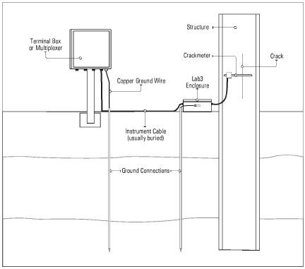
Figure 8: Lightning Protection Scheme