2.Installation
CAUTION! Do not rotate the shaft of the displacement transducer more than 180 degrees. This may cause irreparable damage to the instrument. The alignment pin on the shaft and slot on the body serve as a guide for alignment. Never extend the displacement transducer beyond its working range.
Before installing the gauges in the field, perform a preliminary check by doing the following:
1.Connect the gauge to a readout box. (See Section 3 for information on using readout boxes.)
2.Take a reading. The reading should be stable and in the range of 4000 to 5000 digits.
3.To prevent damage during shipping, the transducer arrives with either a split PVC sleeve taped to the body, or a metal dowel pin inserted into the shaft. Remove the PVC split sleeve or dowel pin. When the shipping spacer is removed and the alignment pin is resting in the alignment slot the reading should be in the range of 2000 to 3000.
4.A check of electrical continuity can be made using an ohmmeter. The resistance between the two lead wires (usually red and black) should be around 180 ohms. Remember to add the cable resistance at approximately 48.5Ω per km (14.7Ω per 1000') at 20 °C. Multiply this factor by two to account for both directions.
5.Using an ohmmeter check the resistance between the two thermistor wires (usually white and green). Use Appendix B to convert the resistance to temperature. Compare the result to the current ambient temperature.
6.Resistance between any conductor and the shield should exceed two megohms.
2.2Displacement Transducer Installation
1.Be sure to place the alignment pin of the transducer shaft into the alignment slot during installation. This will prevent the internal wire from twisting.
2.With the #10-32 thread of the transducer shaft pressed against the shaft-mounting device, rotate the transducer approximately 16 turns to tighten the transducer shaft onto the mounting device. Do not rotate the gauge tube relative to the shaft while securing.
3.Attach the red and black gauge leads to the readout box. Select position B. (See Section 3 for readout instructions.)
4.Gently pull on the transducer housing until the desired reading is obtained, see Table 1. Never extend the shaft further than the range of the gauge. The transducer also may be damaged if it is allowed to free fall through its stroke.
5.Hold the desired reading and secure the cable side of the gauge against or inside the mounting device. The transducer can be secured by using a Swagelok male connector with nylon front and back ferrules. Tighten the Swagelok connector per the instructions in Section 2.3.
6.Initial readings must be taken and carefully recorded along with the temperature at the time of installation. These readings serve as a reference for subsequent deformation calculations.
|
Digit Change |
Minimum |
Maximum |
Midrange |
1/3 Compression |
1/3 Extension |
|
|
Standard 12, 25, and 50 mm |
5000 |
2000 |
7000 |
5000 |
6500 |
4000 |
|
Standard 100 and 150 mm |
5000 |
2000 |
7000 |
5000 |
6500 |
4000 |
|
Slim 12, 25, and 50 mm |
10000 |
3000 |
13000 |
8000 |
6000 |
9000 |
table 1: Model 4450 Reading versus Position in the Range
2.3Swagelok Tube Fitting Instructions
These instructions apply to 25 mm (1") and smaller fittings.
1.Fully insert the tube into the fitting until it bumps against the shoulder.
2:
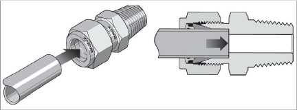
Figure 2: Tube Insertion
2.Rotate the nut until it is finger-tight. (For high-pressure applications as well as high-safety-factor systems, further tighten the nut until the tube will not turn by hand or move axially in the fitting.)
3.Mark the nut at the six o'clock position.
3:
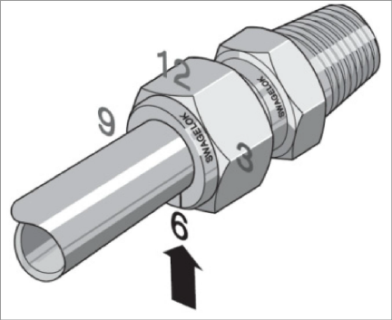
Figure 3: Make a mark at six o'clock
4.While holding the fitting body steady, tighten the nut one and one-quarter turns until the mark is at the nine o'clock position.
Note: For 1/16", 1/8", 3/16", and 2, 3, and 4 mm fittings, tighten the nut three-quarters of a turn until the mark is at the 3 o'clock position
4:
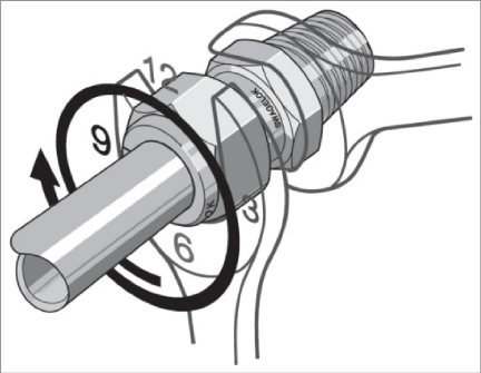
Figure 4: Tighten One and On Quarter Turns
Swagelok tube fittings may be disassembled and reassembled many times.
Warning: Always depressurize the system before disassembling a Swagelok tube fitting.
1.Prior to disassembly, mark the tube at the back of the nut, then make a line along the nut and fitting body flats. These marks will be used during reassembly to ensure the nut is returned to its current position.
5:
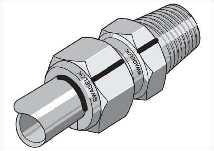
Figure 5: Marks for Reassembly
2.Disassemble the fitting
3.Inspect the ferrules for damage and replace if necessary. If the ferrules are replaced the connector should be treated as a new assembly. Refer to the previous section for installation instructions.
4.Reassemble the fitting by inserting the tube with pre-swaged ferrules into the fitting until the front ferrule seats against the fitting body.
6:
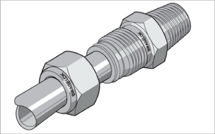
Figure 6: Ferrules Seated Against Fitting Body
5.While holding the fitting body steady, rotate the nut with a wrench to the previous position as indicated by the marks on the tube and the connector. At this point, there will be a significant increase in resistance.
6.Tighten the nut slightly.
7:
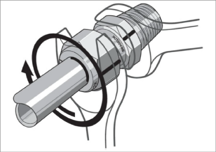
Figure 7: Tighten Nut Slightly
2.4Cable Installation and Splicing
The cable should be routed to minimize the possibility of damage due to moving equipment, debris or other causes. The cable can be protected by the use of flexible conduit, which can be supplied by geokon.
Terminal boxes with sealed cable entries are available from geokon for all types of applications. These allow many gauges to be terminated at one location with complete protection of the lead wires. The interior panel of the terminal box can have built-in jacks or a single connection with a rotary position selector switch. Contact geokon for specific application information.
Because the vibrating wire output signal is a frequency rather than a current or voltage, variations in cable resistance have little effect on gauge readings; therefore, splicing of cables has no ill effects, and in some cases may in fact be beneficial. The cable used for making splices should be a high quality twisted pair type, with 100% shielding and an integral shield drain wire. When splicing, it is very important that the shield drain wires be spliced together. Always maintain polarity by connecting color to color.
Splice kits recommended by geokon incorporate casts, which are placed around the splice and are then filled with epoxy to waterproof the connections. When properly made, this type of splice is equal or superior to the cable itself in strength and electrical properties. Contact geokon for splicing materials and additional cable splicing instructions.
Cables may be terminated by stripping and tinning the individual conductors and then connecting them to the patch cord of a readout box. Alternatively, a connector may be used which will plug directly into the readout box or to a receptacle on a special patch cord.
Care should be exercised when installing instrument cables to keep them as far away as possible from sources of electrical interference such as power lines, generators, motors, transformers, arc welders, etc. Cables should never be buried or run alongside AC power lines; they will pick up the noise from the power cable, which will likely cause unstable readings. Contact the factory concerning filtering options available for use with the geokon dataloggers and readouts.
Unlike numerous other types of instrumentation available from geokon, displacement transducers do not have any integral lightning protection components, such as transorbs or plasma surge arrestors. Usually this is not a problem, however, if the instrument cable is exposed, it may be appropriate to install lightning protection components, as the transient could travel down the cable to the gauge and possibly destroy it.
Suggested Lightning Protection Options:
■If the instrument is connected to a terminal box or multiplexer, components such as plasma surge arrestors (spark gaps) may be installed in the terminal box/multiplexer to provide a measure of transient protection. Terminal boxes and multiplexers available from geokon provide locations for the installation of these components.
■Lighting arrestor boards and enclosures are also available from geokon. These units install where the instrument cable exits the structure being monitored. The enclosure has a removable top to allow the customer to service the components or replace the board in the event that the unit is damaged by a lightning strike. A connection is made between the enclosure and earth ground to facilitate the passing of transients away from the displacement transducer. See Figure 8.
■Plasma surge arrestors can be epoxied into the instrument cable, close to the transducer. A ground strap then connects the surge arrestor to an earth ground, such as a grounding stake or the rebar itself.
Consult the factory for additional information on available lightning protection.
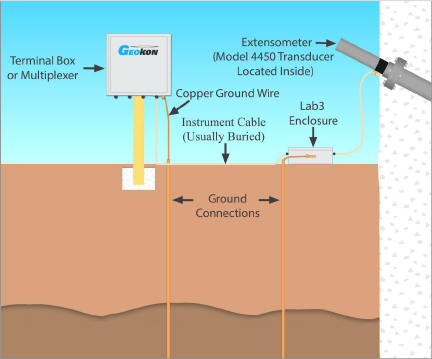
Figure 8: Lightning Protection Scheme