6.Data Reduction
6.1Calculation of Sensor Elevation
Readings can be used to calculate the elevation of the sensor and to plot them on a graph versus time. The graph should also show the elevation of the fill above the sensor at the time of each reading. A plot of temperature can also be included. For the standard 4655 settlement system, using type 4500SV or 4500ALV transducers, the readings will get smaller as the sensors settle relative to the reservoir.
For these sensors, the elevation (E) of the sensor is given by:
E = E0 − (R1 − R0) G + ΔERES
equation 1: Elevation
Where:
ΔERES is any change of the fluid level inside the reservoir sight glass. If the level of the fluid falls, ΔERES is negative. If the level of the fluid rises, ΔERES is positive.
E0 is the sensor elevation at installation
R0 is the initial sensor reading
R1 is the subsequent sensor reading
G is the calibration factor supplied with the sensor
A typical calibration sheet as, supplied by the factory, is shown in Figure 13.
As an example:
E0 = 541.62 meters
R0 = 9030
R1 = 8800
G = −0.001697 meters/digit
ΔERES = −10 mm (i.e. the level of water in the reservoir sight tube is 10 mm lower than the level measure at the time of the initial reading).
Therefore, the new sensor elevation is:
E = 541.62 − (8800−9030) x (−0.001697) + (−0.010)
E = 541.22 meters
In other words, there has been a settlement of 0.40 meters.
Note: The calibration sheet shown in Figure 13 was developed using a simple manometer and is good only over a range of three meters height differential between reservoir and sensor. If this range is exceeded by the initial setup or by large amounts of settlement, then there are two options:
1.Continue to use the settlement system calibration sheet shown in Figure 13.
2.Use the Pressure Transducer calibration sheet supplied with the equipment (Figure 14), which was developed by calibrating the pressure sensor itself over a wider range.
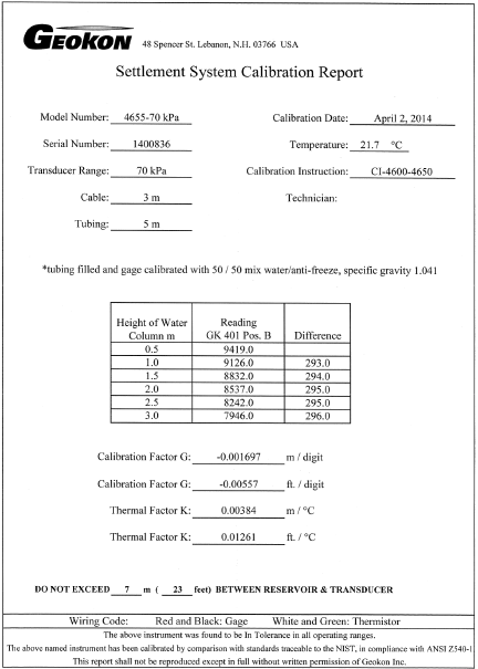
Figure 13: Typical Calibration Report
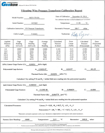
Figure 14: Typical Pressure Transducer Calibration Sheet
6.2Correction for Settlement or Heave of the Reservoir Terminal
Periodic level surveys should be made of the elevation of the fixture on which the reservoir terminal is located. Any measured settlement of the reservoir should be subtracted from the calculated sensor elevations.
6.3Corrections for Temperature
Temperature effects on liquid volume (liquid density) and on the expansion and contraction of the liquid confines can be quite complex and, in some ways, self-canceling. Liquid lines in fills are generally well insulated; therefore, temperature effects tend to be insignificant. Systems exposed to the atmosphere and to sunlight can suffer from rapidly changing temperatures at different parts of the system causing significant fluctuation of the readings. In such cases, precautions may be necessary to obtain readings at times of maximum temperature stability.
Temperature effects on the sensor can be corrected for but are usually quite insignificant especially if the sensor is buried.
The temperature correction to the elevation (ET) is given by:
E = E0 − [(R1 − R0) G + (T1 − T0) K] + ΔERES
equation 2: Temperature Correction
Where:
T0 is the initial temperature.
T1 is the current temperature in ºC
K is the temperature correction factor in meters/ºC.
A thermal factor for the sensor alone is given on the calibration sheet. A thermal factor for the entire system could be determined empirically by measuring the temperature as well as the sensor outputs at times when no settlement is taking place and then calculating the K factor from the slope of the line of a plot of temperature v readout digits x gauge factor.