2.Installation Procedures
Most installations are in fills and embankments where the sensor and cables are buried. Elsewhere the cables and sensors may be attached directly to structures undergoing settlement of heave. The reservoir location must always be at a higher elevation then the sensor and higher than any part of the liquid filled connecting tube.
Prefilled systems are usually delivered with de-aired antifreeze solution already in the liquid lines. An extra length of small diameter tubing is connected to the outer ends of the liquid lines to allow the system to breath during transportation while simultaneously protecting the sensor from being over-ranged by temperature or pressure fluctuations and preventing the entry of air bubbles into the main liquid lines.
Alternatively, systems may be provided with the tubing empty for filling in the field.
The sensor is usually attached to a settlement plate using the bracket(s) provided.
The settlement plate might be attached directly to a structure, using bolts. In the case of installation in fills, a smooth, flat-bottomed excavation should be made about 300 to 600 mm (12 to 24") deep. The sensor plate is placed on this flat surface and covered with fine material, similar to the fill, with all particles over 10 mm (0.4") in size removed. This material should be tamped down around the cell until the excavation is filled back to the original ground surface. The elevation of the settlement plate should be measured at the time of the installation using conventional level survey techniques. Check also that the sensor is still functioning after tamping.
2.2Installing the Cables and Liquid Filled Tubes
Cables and tubing need to be placed in a trench approximately 300 to 600 mm (12 to 24") deep. The trench should not undulate, and individual cables and tubes should be laid side by side without touching or crossing each other. In no place should the tubing be higher than the reservoir location. Before backfilling the trench, examine the tubing for signs of air bubbles. If any are noted, the tubing will need to be flushed before initial readings are taken.
Compact the material in the trench around the cables. Do not allow large angular pieces of rock to rest directly on the cable. To prevent migration of water along the trench, bentonite plugs can be constructed at intervals.
Trenches in earth dam embankments should never penetrate entirely through the clay core. Compaction of the fill above the cables can proceed in a normal manner when the cover exceeds 600 mm (24") depth. Where cables are not buried, they should be adequately supported along their length to prevent undulations. They should also be protected from direct sunlight and insulated from rapid temperature fluctuations by encasing them in Styrofoam or urethane foam, etc.
2.3Installing the Reservoir, Connecting the Sensor Tubes and Vent Tube
The reservoir should be installed on stable ground or at a location that can be level surveyed. The terminal housing should be affixed to stakes grouted firmly into the ground or preferably into a concrete pad poured at a location. The elevation of the reservoir pad should be surveyed and recorded at the time of installation. The reservoir should never be located where it is exposed to direct sunlight.
To fill the reservoir, first make sure that the valve at the bottom is closed, then completely remove the vent line Swagelok fitting from the top and half-fill the reservoir with antifreeze solution (supplied) using the syringe supplied. To avoid foaming, poke the tube from the syringe to the bottom of the reservoir and keep it below the surface of the liquid while filling.
The sensor tubes are shipped full of de-aired antifreeze solution. One tube is capped and to the other tube is attached a long, small-diameter breather tube which is also full of antifreeze solution. The purpose of the breather tube is to prevent air from entering the sensor tube during shipment while at the same time allowing the barometric pressure to equalize inside and outside the sensor. It ensures that when the cap and the breather tube are removed from the ends of the sensor tubing air is not sucked into the tubing by a built-up negative pressure. When connecting the tubes from the sensor to the reservoir do not allow air to be trapped inside the tubing.
Installation is as follows:
1.With the reservoir valve closed, remove one of the caps from the fitting at the base of the reservoir, as well as the cap that does not have the breather tube from the end of the sensor tube.
2.Make sure that water is oozing out of the tube. Elevate the breather tube if necessary.
3.Open the reservoir valve slightly so that water dribbles out.
4.Connect the tube fitting to the mating reservoir fitting and tighten one turn only.
5.Remove the breather tube from the end of the other sensor tube. Make sure that water is oozing out of the tube.
6.Remove the second cap from the other fitting on the base of the reservoir.
7.Slightly open the reservoir valve.
8.While the water is dribbling out connect the second sensor tube fitting and tighten.
9. Remove the cap from the end of the vent line.
10.Make sure that the vent line to the sensor is not blocked. This can be checked using an aspirator bulb, (or simply by sucking), to draw a vacuum on the vent line while observing the sensor reading change on the GK-404 or GK-405 readout box.
11.Attach the vent line to the vent line manifold using the Swagelok fittings.
Follow the instructions in Appendix D to ensure the Swagelok fittings are tightened properly!
12.Add fresh desiccant to the desiccant chamber (or the vent line manifold).
13.Add more liquid to the reservoir to bring up to the half-full point. A few drops of light oil added through the top of the reservoir will prevent evaporation from the liquid surface.
14.Reconnect the vent line fitting to the top of the reservoir.
2.4.1Single and Two-Channel Reservoirs (Models 4650-4A & 4650-4B)
1.Slide the sensor cable(s) into the reservoir through the entry in the bottom of the enclosure.
2.Remove the PCB from the reservoir by unscrewing the four Phillips head screws that hold it in place.
3.Wire the conductors of the cable into the "Gauge 1" terminal block by pressing down on an orange tab, inserting the bare end of the conductor into the terminal block, and then releasing the tab. For two-channel models, repeat this process with the second sensor on the "Gauge 2" terminal block. Refer to Figure 5 and Table 1 below for sensor wiring information.
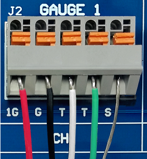
Figure 5: Terminal Connections
|
Position |
Color |
Description |
|
1G |
RED |
Vibrating Wire + |
|
G |
BLACK |
Vibrating Wire - |
|
T |
WHITE |
Thermistor + |
|
T |
GREEN |
Thermistor - |
|
S |
BARE |
Analog Ground (shield) |
table 1: One & Two-Channel Sensor Wiring
4.Gently pull on each conductor to make sure it is secure.
5.If a datalogger is being used, the "Logger" terminal block(s) and the "Local Therm" terminal block to the desired channels on the datalogger.
6.Reinstall the PCB into the reservoir.
2.4.2Three Channel Reservoirs (Model 4650-4C)
1.Slide the sensor cables into the reservoir through the entry in the bottom of the enclosure.
2.Remove the switch plate from the reservoir by unscrewing the four Phillips head screws that hold it in place.
3.Remove the plastic bag of spade crimps from the back of the switch plate. Crimp a spade crimp onto the end of each conductor of all three sensors.
4.Wire each conductor of the sensors to the terminal strip by loosening a Phillips head screw, inserting the spade crimp of the conductor under the head of the screw, and then tightening the screw. The terminal strip wiring is shown in Table 2 and Figure 6.
5.Reinstall the PCB into the reservoir.
|
Gauge # |
Position |
Color |
Description |
|
1 |
1G |
RED |
Vibrating Wire + |
|
1 |
G |
BLACK |
Vibrating Wire - |
|
1 |
T |
WHITE |
Thermistor + |
|
1 |
T |
GREEN |
Thermistor - |
|
1 |
S |
BARE |
Analog Ground (shield) |
|
2 |
2G |
RED |
Vibrating Wire + |
|
2 |
G |
BLACK |
Vibrating Wire - |
|
2 |
T |
WHITE |
Thermistor + |
|
2 |
T |
GREEN |
Thermistor - |
|
2 |
S |
BARE |
Analog Ground (shield) |
|
3 |
3G |
RED |
Vibrating Wire + |
|
3 |
G |
BLACK |
Vibrating Wire - |
|
3 |
T |
WHITE |
Thermistor + |
|
3 |
T |
GREEN |
Thermistor - |
|
3 |
S |
BARE |
Analog Ground (shield) |
table 2: Three & Four-Channel Sensor Wiring

Figure 6: Switch Panel Wiring
Initial readings must be taken with great care; they are the base line readings to which all subsequent readings are compared. For optimum accuracy, allow 2 – 3 weeks for the system to stabilize (to permit the underlying soil to accommodate the self-weight of the sensor and tubing, and for the post supporting the reservoir to achieve fixity) before taking the initial reading R0.
It is also important to allow the system to come to thermal equilibrium, and that the liquid filled tubes be at a constant temperature. If the tubes are not completely buried the readings should be taken at a time when the temperature is relatively constant (first thing in the morning, before sun up). Readings should never be taken when the tubes are exposed to direct sunlight. In addition, there should be no air bubbles in the liquid tubes. If air bubbles are detected the tubes should be flushed before the initial readings are taken. If there is any doubt, take readings, flush the tubing, and take readings again. Repeat if necessary, until the readings are stable. (See Section 3 for readout instructions.) Always record the ambient temperature when taking readings.
Take careful measurement of the elevation of the liquid level inside the reservoir sight tube. Make a mark on the tube opposite the liquid level. This will serve as a quick visual check on any fluctuations and enable a quick means of measuring the magnitude of the change. For correction of subsequent calculations of settlement, see Section 4. (Reservoir level fluctuations may be due to temperature or pressure fluctuations or due to leakage.)