1.Introduction
Earth Pressure Cells, sometimes called Total Pressure Cells or Total Stress Cells are designed to measure stresses in soil or the pressure of soil on structures. Cells will respond not only to soil pressures but also to ground water pressures or to pore water pressure, hence the term total pressure or total stress. A simultaneous measurement of pore water pressure (μ), using a piezometer, is necessary to separate the effective stress (σ') from the total stress (σ) as defined by Terzaghi's principle of effective stress:
σ' = σ - μ
equation 1: Terzaghi’s Principle of Effective Stress
These parameters coupled with the soil strength characteristics will determine soil behavior under loads.
Earth pressure cells of the type described here are the hydraulic type; two flat plates are welded together at their periphery and are separated by a small gap filled with a hydraulic fluid. The earth pressure acts to squeeze the two plates together thus building up a pressure inside the fluid. If the plates are flexible enough (i.e., if they are thin enough relative to their lateral extent), then at the center of the plate the supporting effect of the welded periphery is negligible, and it can be stated that at the center of the cell the external soil pressure is exactly balanced by the internal fluid pressure.
This is true only if the deflection of the plates is kept to a minimum and thus it is important that the cell be stiff. This in a practical sense means that the fluid inside the cell should be as incompressible as possible and that the pressure transducer required to measure the fluid pressure should also be stiff having very little volume change under increasing pressure.
Tests conducted by various researchers (as reported by Dunnicliff, 1988) have shown that the introduction of a flat stress cell into a soil mass will alter the stress field in a way dependent on the relative stiffness of the cell, with respect to the soil, and also with respect to the aspect ratio of the cell, i.e., the ratio of the width of the cell to its thickness. A thick cell will alter the stress more than a thin cell. For these reasons, a thin, stiff cell is best, and studies have shown an aspect ratio of at least 20 to 1 to be desirable.
Ideally, the cell ought to be as stiff (compressible) as the soil, but in practice this is difficult to achieve. If the cell is stiffer (less compressible) than the soil, then it will over register the soil pressure because of a zone of soil immediately around the cell which is "sheltered" by the cell and therefore does not experience the full soil pressure. This can be represented schematically as shown in Figure 1.
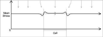
Figure 1: Stress Redistribution, Weak Soil with Stiff Cell
As can be seen there is a stress concentration at the rigid rim but in the center of the cell the soil stress is only slightly higher than the mean soil stress, i.e., only slightly higher than the stress which would obtain were the cell not present.
In a stronger soil, the distressed zone around the edge of the cell is more extensive; therefore, the degree of over registration of the mean stress is greater at the center of the cell. This is represented schematically in Figure 2.
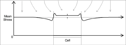
Figure 2: Stress Redistribution, Strong Soil with Stiff Cell
In a stiff soil the cell may be less stiff (more compressible) than the soil, in which case the cell will under register the mean soil stress as the stresses in the soil tend to "bridge" around the cell. This is represented schematically in Figure 3.
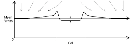
Figure 3: Stress Redistribution, Stiff Soil with Weak Cell
Tests conducted at the University of Ohio (USA) with several different soil types have shown that for geokon cells the maximum degree of over or under registration amounts to 15% of the mean soil stress.
Other factors should be kept in mind. The inherent variability of soil properties, which give rise to varying soil stresses at different locations, and a corresponding difficulty in getting a good sample of the mean stress from a limited number of cell locations. In addition, the response of the cell to its immediate surroundings depends mostly on how closely the soil mass immediately around the cell has the same stiffness or compressibility or the same degree of compaction as the undisturbed soil mass. Installation methods will need to pay particular attention to this detail.
Earth Pressure Cells are constructed from two stainless steel plates welded together around the periphery to leave a narrow space between them. This space is filled with de-aired hydraulic oil, which is connected hydraulically to a pressure transducer. The pressure transducer converts the oil pressure into an electrical signal, which is transmitted through a signal cable to the readout location.
In general, geokon Earth Pressure Cells use an all welded construction; this means the space confining the oil is entirely metal and does not require any o-rings, which tend to trap air and reduce the cell stiffness. The oil is de-aired using a Nold DeAerator, which materially improves the fluid stiffness and the performance of the cell. The pressure transducer normally employed is the geokon Model 4500H, which is available in several different pressure ranges (see Appendix A). The cable is attached to the transducer in a sealed, waterproof manner. For earth pressure cells located inside a soil mass, the cable may be armored and provided with strain relief at the cell to reduce the likelihood of pullout.
Located inside the vibrating wire pressure transducer housing is a thermistor for the measurement of temperature at the cell location. In addition, a tripolar plasma surge arrestor inside the transducer housing protects the vibrating wire pluck and read coils from electrical transients such as may be induced by direct or indirect lightning strikes.
Alternative pressure transducers with voltage (0-100 mV, 0-5 VDC, 0-10 VDC) or current (4 - 20 mA) output are also available for dynamic readout capability. Consult the factory for additional information.
1.3Earth Pressure Cell Construction
1.3.1Model 4800 Earth Pressure Cells
Model 4800 Earth Pressure Cells may be rectangular or circular in shape. The standard size for the rectangular Model 4800 is 150 mm × 250 mm (6" × 10"), for the circular it is 230 mm (9") in diameter. Standard thickness for both styles is 6 mm (aspect ratio ≈ 40). For laboratory tests, smaller, thinner cells can be manufactured. Contact the factory for additional information.
4:
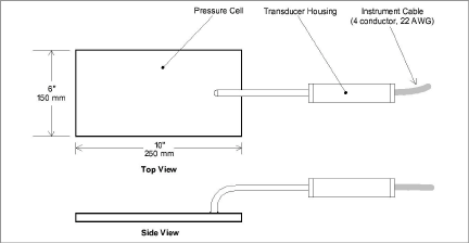
Figure 4: Model 4800 Rectangular Earth Pressure Cell
5:
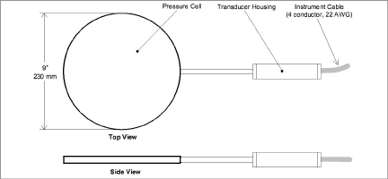
Figure 5: Model 4800 Circular Earth Pressure Cell
1.3.2Model 4810 Contact ("Fat Back") Pressure Cell
Model 4810 Earth Pressure Cells are designed for measuring soil pressures on structures. One of the plates is thick and designed to bear against the external surface of the structure in a way that will prevent flexure of the cell. The other plate is thin and reacts to the soil pressure.
6:
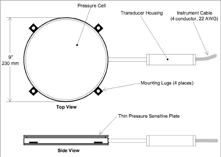
Figure 6: Model 4810 Contact Pressure Cell
1.3.3Model 4815 Granular Soil Type Pressure Cell
The Model 4815 Pressure Cell uses two thick plates welded together at a flexible hinge that helps provide a more uniform pressure distribution, which effectively reduces the severity of point loading when used in granular materials.
7:
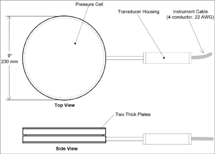
Figure 7: Model 4815 Granular Soil Type Pressure Cell
1.3.4Model 4820 Earth Pressure "Jackout" Cell
Model 4820 Earth Pressure Cells are designed specifically for the measurement of soil pressures on the back side of slurry walls. The pressure transducer housing is connected directly and perpendicular to the thick back plate.
8:
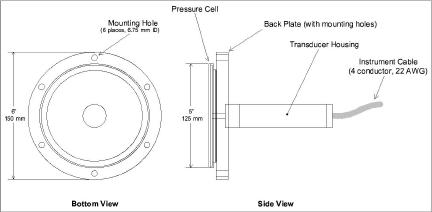
Figure 8: Model 4820 Jackout Pressure Cell
1.3.5Model 4830 Push-In Pressure Cell
Model 4830 Push-In Pressure Cells are designed to be pushed in place for the measurement of total pressures in soils and earth fills. A thread is provided on the end of the cell to allow for installation using lengths of pipe or drill rods.
9:
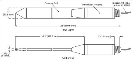
Figure 9: Model 4830 Push-In Pressure Cell