Appendix E.Load Cell Calibrations - Effects Of Bearing Plate Warping
Load cells used to measure loads during testing of tiebacks, driven piles, and drilled shafts, give calculated loads that are frequently in disagreement with loads calculated based on hydraulic jack pressure and piston area. Because of this, there is a general lack of confidence in load cell data and the fault is often ascribed to manufacturing defects, or to improper, inaccurate calibration procedures. Nevertheless, it is also well known that the effects of eccentric loading and uneven and/or warped bearing plates do have a profound effect on load cell readings. The purpose of this technical note is to provide some insight into these effects.
E.2Load Cell Calibration Procedures
The usual calibration procedure is to use a testing machine to apply a load to a load cell. The measured load cell output is then correlated against the known applied load as measured by the testing machine. Usually, the testing machine has a hydraulic pressure applied to a piston of known cross section area. The testing machine is checked out periodically by running tests on a load cell traceable to NIST and there is generally little doubt about the accuracy of the testing machine. Accuracy's of ¼% FS ½% FS or 1% FS are normal.
Usually, the calibration tests are performed between large, flat parallel platens in the testing machine so that there is no bending of the platens, only the elastic compression in the zone immediately bearing against the load cell.
Such a state of affairs may not exist on the job site since the bearing surfaces next to the load cell are usually much less rigid, and liable to bending.
This bending is particularly apparent if there is a mismatch in size between the load cell and the hydraulic jack. If the hydraulic jack is larger than the load cell there is a tendency for it to try to wrap the intervening bearing plate around the load cell. If the hydraulic jack is smaller than the load cell it will try to push the intervening bearing plate through the hole in the load cell.
Thicker bearing plates will bend less, but the effect will never be entirely eliminated. The consequence of this bending can be quite large since the effect on the load cell is to cause it to either barrel out at its midsection if the jack is too small, or pinch in at its midsection if the jack is too big. For vibrating wire load cells, the gauges are usually located in the center of the cell wall, on the neutral axis, thereby minimizing these effects.
E.4Effects of Jack Size on Load Cell Reading
A series of tests were conducted in a testing machine to investigate the magnitude of the effect of jack size on load cell readings.
A load cell with a bearing surface of 4" ID, 5¾" OD was used.
Simulated jack A had a bearing surface of 2" ID, 4" OD.
Simulated jack B had a bearing surface of 4" ID, 5¾" OD.
Simulated jack C had a bearing surface of 6" ID, 8" OD.
The maximum applied load was 150 tons.
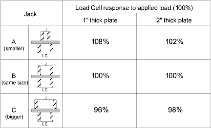
table 7: Effects of Jack Sizing on Readings
From the results, it can be seen that if the jack is smaller than the load cell, the load cell will over-register, while a jack bigger than the load cell will cause the load cell to under-register. The effect is bigger if the bearing plate between jack and load cell is thinner.
The correct bearing plate thickness will of course depend on the extent of the mismatch between jack and load cell. However, as a rough rule of thumb the following thickness should be required:
100-200 kip load: 25 mm (1") thick
Up to 400 kip load: 37 mm (1.5") thick
Up to 1000 kip load: 50 mm (2") thick
Up to 2000 kip load: 75 mm (3") thick
The consequences of all this would seem to indicate that, for best results, the load cell calibration should be performed with the actual hydraulic jack that will be used, both being placed in the testing machine at the same time. If that is not possible, the load cell should be loaded through a ring, having the same dimensions as the hydraulic jack bearing surface, positioned on the other side of a bearing plate of the correct thickness. In this way, one of the variables affecting the agreement between load cell readings and hydraulic jack readings can be removed and the agreement should be that much closer.
This technical note has addressed only the subject of the size mismatch between load cells and hydraulic jacks. Other factors affecting the agreement between load cell readings and hydraulic jack load are important, thus frictional losses within the hydraulic jack can cause under-registering of jack load indications by as much as 15%. (Dunnicliff 1988' Section 13.2.6)
Also, annular style load cells are susceptible to end effects and eccentrically applied loads. The height of the load cell should exceed four times the wall thickness of the annulus, and at least three strain gauges should be used, increasing in number as the size of the load cell increases, up to six total.
References:
J. Dunnicliff. 1988. Geotechnical Instrumentation for Monitoring Field Performance, John Wiley & Sons, New York, NY: 577pp.