3.1GK-404 Vibrating Wire Readout
The Model GK-404 VW Readout is a portable, low-power, hand-held unit that is capable of running for more than 20 hours continuously on two AA batteries. It is designed for the readout of all geokon vibrating wire instruments, and is capable of displaying the reading in digits, frequency (Hz), period (µs), or microstrain (µε). The GK-404 also displays the temperature of the transducer (embedded thermistor) with a resolution of 0.1 °C.
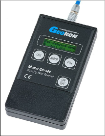
Figure 6: GK-404 Readout
1.Attach the flying leads by aligning the red circle on the silver Lemo connector with the red line on the top of the GK-404 (see the figure below). Insert the Lemo connector into the GK-404 until it locks into place.
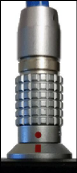
Figure 7: Lemo Connector to GK-404
2.Connect each of the clips on the leads to the matching colors of the sensor conductors, with blue representing the shield (bare).
3.To turn on the GK-404, press the On/Off button on the front panel of the unit. The initial startup screen will display.
4.After a delay, the GK-404 will start taking readings and display them based on the settings of the Pos and Mode buttons.
The unit display (from left to right) is as follows:
■The current position: set by the Pos button, displayed as A through F.
■The current reading: set by the Mode button, displayed as a numeric value followed by the unit of measure.
■Temperature reading of the attached instrument in degrees Celsius.
Use the Pos and Mode buttons to select the correct position and display units for the model of equipment purchased.
The GK-404 will continue to take measurements and display readings until the unit is turned off, either manually or by the Auto-Off timer (if enabled).
For more information, consult the GK-404 manual.
3.2GK-405 Vibrating Wire Readout
The GK-405 Readout is made up of two components:
■The Readout Unit, consisting of a Windows Mobile handheld PC running the GK-405 Vibrating Wire Readout application.
■The GK-405 Remote Module, which is housed in a weather-proof enclosure.
The remote module can be wire-connected to the sensor by means of:
■Flying leads with alligator clips if the sensor cable terminates in bare wires.
■A 10-pin connector.
The two units communicate wirelessly using Bluetooth®, a reliable digital communications protocol. Using Bluetooth, the unit can operate from the cradle of the remote module, or, if more convenient, can be removed and operated up to 20 meters away from the remote module.
The GK-405 displays the thermistor temperature in degrees Celsius.
For further details, consult the GK-405 Instruction Manual.
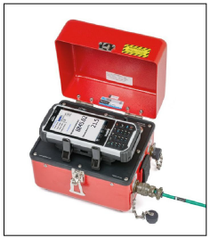
Figure 8: GK-405 Readout
3.2.1Connecting Sensors with 10-Pin Bulkhead Connectors Attached
Align the grooves on the sensor connector (male), with the appropriate connector on the readout (female connector, labeled senor or load cell). Push the connector into place, and then twist the outer ring of the male connector until it locks into place.
3.2.2Connecting Sensors with Bare Leads
Attach the flying leads to the bare leads of a geokon vibrating wire sensor by connecting each of the clips on the leads to the matching colors of the sensor conductors, with blue representing the shield (bare).
Press the power button on the Readout Unit. After start-up completes, a blue light will begin flashing, signifying that the two components are ready to connect wirelessly. Launch the GK-405 VWRA program by doing the following:
1.Tap Start on the hand-held PC's main window.
2.Select Programs.
3.Tap the GK-405 VWRA icon.
After a few seconds, the blue light should stop flashing and remain lit. The Live Readings window will display on the hand-held PC.
Set the Display mode to B.
■For load cells connected with a 10-pin bulkhead connector, choose Sensor Index "AVG". The average digit reading of all strain gauges in the load cell will be displayed.
■For load cells connected with flying leads, choose Sensor Index "1". The digit reading of the currently connected strain gauge will be displayed.
If no reading displays or the reading is unstable, see Section 5 for troubleshooting suggestions.
For more information, consult the GK-405 Instruction Manual.
Due to the lengthy warmup period when first switching on the box it is best to leave the readout in a sleep mode if multiple readings are taken during the course of a day. This is done by first pressing 'Menu' and then select 'Close GK-405' then pressing the Handheld power button momentarily. To switch the readout box off completely hold the power button down for few seconds until a ring tone is heard.
Writing data into a field book for later transferring to a spreadsheet is in many ways the best approach to take. For details concerning storage of the readings in the readout memory, consult the GK-405 Instruction Manual.
If the readout is required in units of load, refer tothe section below.
Before readings can be stored in the readout box, a workspace needs to be created where to identify the load cell and configure its parameters, e.g., gauge factor, zero reading, units, etc. This will need to be done for each load cell.
For each load cell, a sensor file must be created. On the Workspace screen press and hold 'Project Sensors then hit 'Add Sensor'.
1.Hit the keyboard icon at the bottom center of the screen and use the keyboard to enter the Load cell identification name and/or number
2.Select the sensor model number, 4900, from the dropdown menu
3.From the drop-down menu, insert the number of gauges in the load cell.
4.Select the ► arrow to reach the next page
5.Select 'Linear' (If selecting 'Polynomial' follow the instructions for entering the A, B, and C coefficients).
6.Select 'Output Calculation' to G(R1-R0) in the dropdown menu,
7.Using the keyboard set the zero reading equal to the initial Regression Zero shown on the calibration sheet. (See Appendix F for further explanation)
8.Using the keyboard set the 'Gauge Factor' equal to the Gauge Factor given on the calibration sheet. (Do not forget the negative sign.)
9.Leave "Gauge Offset" at zero
10. Select the ► arrow to reach the next page,
11. Select 'Measure' to 'Load'.
12. Select the input units equal to the gauge factor units.
13. Select the desired output units that will show on the display.
14. Select the ► arrow to reach the next page
15. For most application the temperature coefficient is not important in which case leave the 'Sensor Correction' at 'disabled'
16. Select 'Menu' and 'Save the Settings'.
17. Select 'Applications'
18. Select 'Live Readings'
19. Select 'With Selected Sensor' (the same one created in Step 1)
20. The readings should now be in units of load.
21. To store data hit the 'Store' icon on the screen. The readings will be stored under that particular load cell file, the one created in Step 1.
Note that if one of the strain gauges fails a red warning will appear on the display. The readout box will continue to display the average reading of the remaining strain gauges.
At any time in the Live Reading screen, when 'Raw Readings' is selected it is possible to display the reading on each individual strain gauge in the load cell. This can be useful in assessing the degree of eccentricity of the applied load. For further information, consult the GK-405 Instruction Manual.
All geokon vibrating wire instruments are equipped with a thermistor for reading temperature. The thermistor gives a varying resistance output as the temperature changes. The white and green leads of the instrument cable are normally connected to the internal thermistor.
The GK-404 and GK-405 readouts will read the thermistor and display the temperature in degrees Celsius.
To read temperatures using an ohmmeter:
1.Connect an ohmmeter to the green and white thermistor leads coming from the instrument. Since the resistance changes with temperature are large, the effect of cable resistance is usually insignificant. For long cables a correction can be applied equal to approximately 48.5Ω per km (14.7Ω per 1000') at 20 °C. Multiply these factors by two to account for both directions.
2.Look up the temperature for the measured resistance in Appendix B.