The output of the Model 6150F inclinometer sensor is angle of inclination. The standard sensor has a full range of approximately ±15°.
Each sensor is provided with a unique Gauge Factor (G) that is used to calculate the corrected inclination angle (θ) of the sensor:
θ = G(R)
equation 1: Corrected Inclination Angle
Where:
θ = Corrected inclination angle of the sensor
G = Gauge Factor
R = Reading from sensor
To calculate the change in the inclination angle of the sensor, the following equation is used:
Δθ = G(R1-R0)
equation 2: Change in Inclination
Where:
Δθ = Change in the inclination angle of the sensor
G = Gauge Factor
R1 = Current reading from sensor
R0 = Initial or Zero reading from sensor
Positive values are tilts in the direction of the arrows A+ and B+
The lateral displacement (D) of the top of any segment relative to the vertical line running through the bottom of the segment is equal to:
D = Lsinθ
equation 3: Lateral Displacement
Where:
L = The length of the segment
θ = Inclination angle of the sensor
Equation 3 can also be expressed as: D = LsinG(R)
Where:
G = Gauge factor
R = Reading from the sensor
The profile of the borehole is constructed using the cumulative sum of these lateral displacements starting with the bottom segment (L1).
For reference, see the figure below.
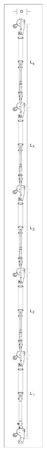
Figure 19: Deflection Intervals
The total lateral displacement of the top of the upper segment (which is usually at the surface), from the vertical line drawn through the bottom of the lower segment (located at the bottom of the borehole), is:
D = L1sinθ1 + L2sinθ2 + L3sinθ3 + L4sinθ4 +L5sinθ5
equation 4: Total Lateral Displacement Calculation
Therefore:
D = L1sinG(R)1 + L2sinG(R)2 + L3sinG(R)3 + L4sinG(R)4 + L5sinG(R)5
and the change in displacement (ΔD) is:
ΔDn = Σn1 LnGnΔRn
equation 5: Deflection Calculation
Where:
Δ R1 = Sensor’s(1) current reading (R1(1)) minus the sensor’s (1) initial, or Zero, reading (R0(1)), or (R1(1)-R0(1)).
Δ R2 = Sensor’s(2) current reading (R1(2)) minus sensor’s (2) initial, or Zero, reading (R0(2)), or (R1(2)-R0(2)).
Repeat for all the other sensors in the string.
Although the system is designed for use in continuous segments with pivots, the sensors can be installed without interconnecting tubing in standard, round tubing or pipe using special friction anchors. In those systems, the assumption is made that the measured deflection occurs over the segment length, the midpoint of which is at the sensor location, and that L is the distance between adjacent midpoints.
Although the temperature dependence of the MEMS tilt meter is close to zero, and usually does not require compensation, it sometimes happens that temperature effects can cause real changes of tilt; therefore, each sensor is equipped with a device for reading the sensor temperature. This enables temperature-induced changes in inclination to be distinguished from inclination due to other sources. The device provides a digital output proportional to the temperature.
Normally, temperature corrections are not required. An important point to note is that sudden changes in temperature will cause both the structure and the sensor to undergo transitory physical changes, which will show up in the readings. The sensor temperature should always be recorded, and efforts should be made to obtain readings when the instrument and structure are at thermal equilibrium. The best time for this tends to be in the late evening or early morning hours.
Since the purpose of the inclinometer installation is to monitor site conditions, factors that may affect these conditions should be observed and recorded. Seemingly minor effects may have real influence on the behavior of the structure being monitored and may give an early indication of potential problems. Some of these factors include, but are not limited to, blasting, rainfall, tidal or reservoir levels, excavation and fill levels and sequences, traffic, temperature and barometric changes, changes in personnel, nearby construction activities, seasonal changes, etc.