The table below shows the function of each of the conductors of geokon RS-485 cables.
|
Instrument Cable Conductors |
Description |
|
Red |
String Power |
|
White |
Communication RS-485+ |
|
Green |
Communication RS-485- |
|
Black |
Ground |
|
Shield |
Analog Ground |
Connect each of the RS-485 string conductors to their respective spring terminal connections on the Addressable Bus Converter, as follows:
1.Connect the red wire lead to the connection labeled 12V (OUT) [RED] on the RS-485 spring terminal.
2.Connect the white wire lead to the connection labeled 485+ [WHITE] on the RS-485 spring terminal.
3.Connect the green wire lead to the connection labeled 485- [GREEN] on the RS-485 spring terminal.
4.Connect the bare wire lead to the connection labeled SHIELD on the RS-485 spring terminal.
5.Connect the black wire lead to the connection labeled GND [BLACK] on the RS-485 spring terminal.
See the figure below.

Figure 2: Connecting RS-485 String to Addressable Bus Converter
To connect the Converter to a TTL-capable device, do the following:
1.Connect the RX wire of the logger/reader to the connection labeled RX [OUT] on the TTL spring terminal.
2.Connect the TX wire of the logger/reader to the connection labeled TX [IN] on the TTL spring terminal.
3.Connect the external 12 volt supply positive (+) and negative (-) wires to the connections labeled 12V and GND on the TTL spring terminal, respectively.
4.Connect the shield wire to the connection labeled SHIELD on the TTL spring terminal as well.
See the figure below.
Note: The TTL signal ground reference MUST be connected to the Addressable Bus Converter ground, as well as to the ground of the external power supply.
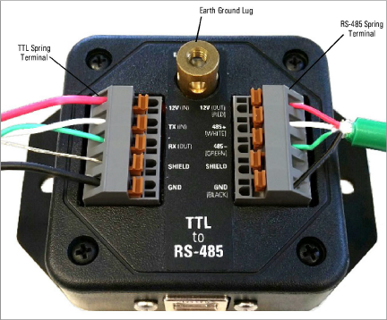
Figure 3: Connecting TTL and External Power to Addressable Bus Converter
Secure the ground strap to the earth ground lug using the brass screw included with the assembly. Attach the other end of the strap to a reliable earth ground point outside of the enclosure.
To connect the Converter via USB, plug one end of a USB Type A to Type B cable into the USB port on a PC, then plug the other end of the cable into the Converter’s USB port. See the figure below.
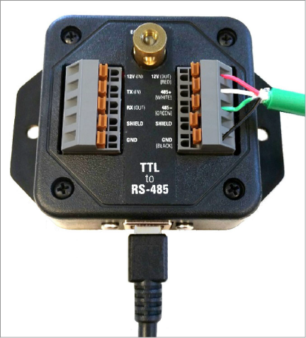
Figure 4: Connecting USB Cable to Addressable Bus Converter
The Addressable Bus Converter has a default bit rate of 115,200 bits per second. However, the Converter supports changing the bit rate, depending on the sensors connected to the RS-485 bus. The TTL, USB, and RS-485 bit rates are all updated automatically when a connection is opened to a USB host.
Note: The bit rate MUST be set using a USB connection. A bit rate change cannot be done over a TTL connection.
To change the bit rate, do the following:
1.Connect the USB cable to the USB port on the Converter.
2.Start the host software on the PC.
3.Set the desired bit rate in the settings of the host program.
4.Open the connection.
The software will write the new bit rate to the Converter’s non-volatile memory. The new bit rate will serve as the default bit rate after the next power-up.
There might be times when no dedicated USB host software is available. An example of this is when the system will be used in a TTL to RS-485 application. For such times a terminal emulator program such as Docklight™ or Hyperterminal™ can be substituted for the USB host software. Do the following:
1.Connect the Converter to a PC using a USB cable.
2.Open the terminal emulator program.
3.Select the COM port and bit rate settings.
4.Open the connection.
Some dataloggers communicate over the TTL connection using inverted logic. When connecting a geokon addressable sensor string to a logger with inverted TTL signals, be sure to configure the Converter to handle this form of communication. Do the following:
1.Remove the two USB connector screws.
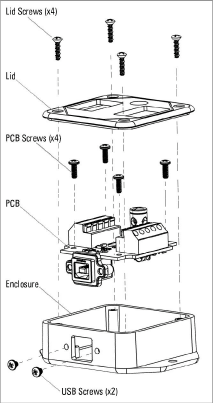
Figure 5: Disassembling the 8020-38 Converter
2.Remove the four enclosure lid screws and remove the lid.
3.Remove the four PCB mounting screws.
Warning: Use ESD protection for the remaining steps to avoid causing damage to the PCB.
4.Remove the PCB from the enclosure.
5.Flip the PCB upside down and move the 'INV TTL' switch to the ON position.
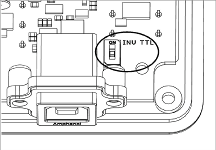
Figure 6: TTL Inversion ON/OFF switch
6.Re-assemble the Converter by following the previous steps in reverse.
For your convenience this setting can be applied by geokon prior to shipping out the Converter.