2.Network Components
Cellular Gateway models send their data to geokon’s safe and secure Cloud via a cellular data connection, and are available with LTM or 3G connections.
The cellular connectivity is included in the data plan and no user configuration is necessary. Users can commission or decommission their own systems via geokon’s online portal.
The gateway stores battery and temperature data sent from the loggers, and data from the sensors, but it does not possess sensor-reading functionality on its own.
2:
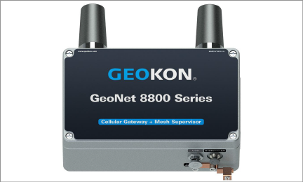
Figure 2: 880X-XX-XXX-USB
Local Gateway models lack an integrated cellular module, but they are otherwise functionally the same as Cellular Gateway models.
This model features an RS-232 connector, for transferring data using an RS-232 cable to a PC running Agent software.
3:
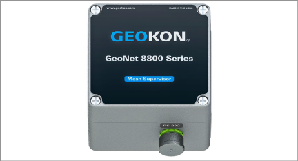
Figure 3: RS-232 Local Gateway (8800-XX-SUP-232)
This model features a USB connector, for transferring data using a USB cable to a PC running Agent software.
4:
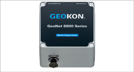
Figure 4: USB Local Gateway (8800-XX-SUP-USB)
A single-channel logger will read one geokon vibrating wire gauge, either via 10-pin cable or via a cable with stripped conductor wires, depending on model.
Though designed to send data wirelessly to a gateway, this model also features a USB connector, for transferring data using a USB cable to a PC running Agent software.
2.3.110-Pin Connector (880X-XX-01C-10P)
For use with gauges with 10-pin cable connectors.
5:
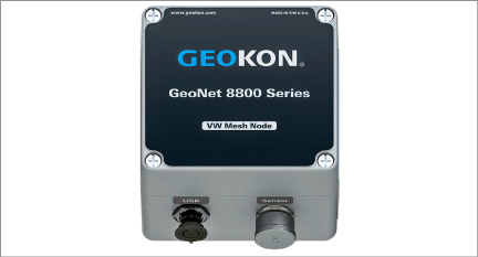
Figure 5: 10-Pin Single Channel Logger (8800-XX-01C-10P)
2.3.2Gland Seal (880X-XX-01C-CBL)
For use with gauge cables that have stripped conductor wires. The gauge cable passes through an external cable gland and is wired into the terminal block.
6:
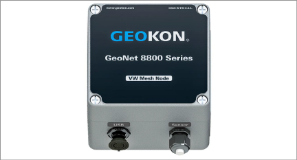
Figure 6: Gland Seal Single Channel Logger (8800-XX-01C-CBL)
Multiple-channel loggers will read up to eight geokon vibrating wire gauges, depending on model, via cables with stripped conductor wires. The cables pass through external cable glands and are wired into the terminal blocks.
Multiple-channel loggers function in the same manner as other loggers.
Though designed to send data wirelessly to a gateway, these models also feature a USB connector for transferring data using a USB cable to a PC running Agent software, just as with single-channel loggers.
2.4.1Single-Channel (8800-XX-ADR-CBL)
For use with sensor cables with stripped and tinned ends. The sensor cable passes through an external cable gland and is wired into the terminal block.
7:

Figure 7: Mesh Addressable Logger (8800-XX-ADR-CBL)
2.4.2Four-Channel (880X-XX-04C-CBL)
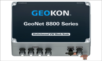
Figure 8: Four-Channel Logger (880X-XX-04C-CBL)
Note: When inserting stripped conductor wires into the terminal blocks, be sure to connect them to the VW terminal blocks.
A four-channel logger can be configured as follows:
|
Model |
Maximum Number of Gauges |
Maximum Number of Load Cells |
|
880X‑XX‑04C‑CBL |
Four |
One 3‑gauge or one 4‑gauge load cell |
table 2: Four-Channel Logger Gauge/Load Limits
2.4.3Eight-Channel (880X-XX-08C-CBL)
9:
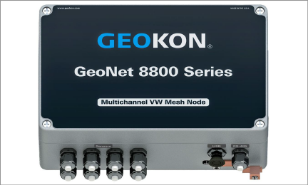
Figure 9: Eight-Channel Logger (880X-XX-08C-CBL)
Note: When inserting stripped conductor wires into the terminal blocks, be sure to connect them to the VW terminal blocks.
An eight-channel logger can be configured as follows:
|
Model |
Maximum Number of Gauges |
Maximum Number of Load Cells |
|
880X‑XX‑08C‑CBL |
Eight |
One 3‑gauge and one 4‑gauge load cell |
table 3: Eight-Channel Logger Gauge/Load Limits
Addressable loggers are protected from environmental contaminants by a rugged IP66 die cast aluminum enclosure. An earth ground terminal is provided on the exterior of the enclosure to protect against lightning and other large, transient voltages.
2.5Mesh Tilt Logger (880X-XX-TLT-NAP)
Tiltmeters are designed for permanent long-term monitoring of changes in tilt of structures such as dams, embankments, foundation walls, retaining walls, buildings, and the like.
geokon biaxial tiltmeter loggers contain an integrated tiltmeter sensor, and communicate with the gateway in the same manner as other loggers.
The two axes of the tiltmeter have a range of ±90°, based on a starting position of 0°. To achieve the best linearity, mount the tiltmeter so the back of the enclosure is as close as possible to vertical, and the bottom of the enclosure is as close as possible to horizontal.
Though designed to send data wirelessly to a gateway, this model also features a USB connector for transferring data using a USB cable to a PC running Agent software, the same as with the single-channel loggers.
10:
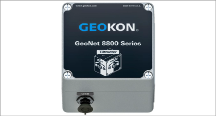
Figure 10: Mesh Tilt Logger (880X-XX-TLT-NAP)
Gateways and loggers are shipped with the following accessories:
■One omni-directional antenna (2.1 dBi). For other antenna options, please contact geokon technical support.
■Two D cell alkaline batteries
■Four desiccant packs
Gateways are shipped with the following additional accessories:
■Set of two screwdrivers, one Phillips head and one flat-head
■One RS-232 or USB cable (depending on the model purchased)
■USB to RS-232 adapter cable (RS-232 models only)
2.7Compatibility With Legacy GeoNet Products
8800-XX-XXX-XXX models are compatible with the following legacy GeoNet products:
|
Legacy Part Number |
New Part Number |
|
8800-4-1A |
8800-NA-SUP-232 |
|
8800-4-2A |
8800-NA-SUP-USB |
|
8800-3-1A |
8800-NA-01C-CBL |
|
8800-3-2A |
8800-NA-01C-10P |
|
8800-6-1A |
8800-NA-ADR-CBL |
|
8800-4-1B |
8800-BZ-SUP-232 |
|
8800-4-2B |
8800-BZ-SUP-USB |
|
8800-3-1B |
8800-BZ-01C-CBL |
|
8800-3-2B |
8800-BZ-01C-10P |
|
8800-6-1B |
8800-BZ-ADR-CBL |
|
8800-4-1C |
8800-AU-SUP-232 |
|
8800-4-2C |
8800-AU-SUP-USB |
|
8800-3-1C |
8800-AU-01C-CBL |
|
8800-3-2C |
8800-AU-01C-10P |
|
8800-6-1C |
8800-AU-ADR-CBL |
table 4: Legacy Compatibility Chart
Many networks use a star topology, where all loggers can send data directly to the gateway. Other networks use a mesh topology, in which loggers will relay data from any logger that might be blocked, or out of range from the gateway.
GeoNet networks are self-healing. This means that GeoNet will switch to a mesh topology so that loggers will automatically relay data from troubled loggers to the gateway, if needed.
GeoNet networks are self-configuring, meaning that the switch from a star topology to a mesh topology is automatic, and the loggers will determine for themselves which will relay data to the gateway.
11:
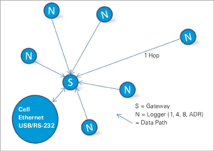
Figure 11: Star Network Topology
12:

Figure 12: Mesh Network Topology
Each transmission from logger to gateway or logger to logger is considered one "hop". Examples of hops are shown in figures above and below. Up to four hops can be made between a logger and the gateway. With the ability to hop comes the ability for the gateway to communicate with loggers that have not established direct radio contact. GeoNet devices can operate around buildings or other barriers using hops.
13:
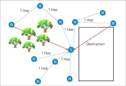
Figure 13: Working Around Obstructions via Hops
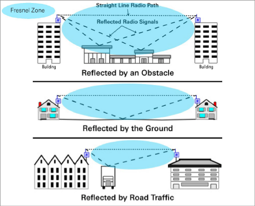
Fresnel Zone
The Fresnel zone is the geographic area between the sending antenna and the receiving antenna. Objects in the Fresnel zone can cause reflections of the transmitted signal. When these reflections arrive at the receiving antenna, they may be out of phase with the signal that took a straight-line path, and this can weaken the straight-line signal.
For optimum performance, geokon recommends creating as much vertical space as possible between the straight-line path and obstacles, including the ground.
The Fresnel zone must be at least 60% obstruction-free to ensure optimal wireless communication. The figure below illustrates the Fresnel zone.
14:
IMPORTANT: If communication cannot be established when GeoNet is deployed to a site, it may be necessary to elevate the devices or their antennas, or to move them to a location where a radio link can be established. This may require extending the readout cable of the attached sensors, or adding an antenna cable extension.