2.Network Installation
Review the GeoNet Installation Tutorial available at the geokon website, https://www.geokon.com/tutorial-videos.
Select the mounting location with care. Certain mounting configurations can hinder or even completely block wireless signal transmission. Refer to Appendix G for more information.
A network must include the supervisor and at least one node that is within radio range of the supervisor. The necessary steps include:
1.Configure the channel.
2.Mount the device.
3.Install the antenna.
4.Install the batteries.
5.Connect the sensor(s).
6.Seal the enclosure.
Channels allow multiple networks to coexist in the same area. All devices are set to communicate on Channel 1 from the factory; this is all that is required for operating a single network in a given area. However, if multiple networks are within radio range of each other, then the networks must be set to different channels, and devices of each network must be set to their respective channel.
To set the channel on a Node or Supervisor:
1.Open the device by unscrewing the four captive screws on the front of the enclosure. Ensure that no dirt, water, or other contaminants are allowed to enter the enclosure.
2.Set the channel select DIP switch (shown in the figure below) to any of the twelve valid positions listed in Table 15 in Appendix C.
11:
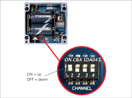
Figure 11: Channel Select Switches
3.Press the Reset button.
12:
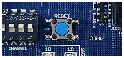
Figure 12: Reset Button
4.Devices will communicate only with others that have been set to the same channel. To prevent erratic behavior, there can be only one supervisor on a particular channel. Supervisors in radio range of each other must operate using different channel settings.
The built-in mounting plate is designed to be used with U-Bolts, hose clamps, screws, bolts, etc. Devices should be mounted vertically, with the antenna pointing up.
Select the mounting location with care. Certain mounting configurations can hinder or even completely block wireless signal transmission. See Appendix G.
Remove the rubber cap from the antenna mount. Position the antenna on the mount and then rotate the antenna in a clockwise direction until tightened.
When replacing batteries in an existing network, ensure that the network is in deployment mode prior to removing the batteries. See Section 5.3 for more information on battery replacement.
Install the batteries as follows:
1.Open the device by unscrewing the four captive screws on the front of the enclosure. Ensure that no dirt, water or other contaminants are allowed to enter the enclosure.
2.Set the three-position battery select switch to the OFF (middle) position (see the figure below).
13:
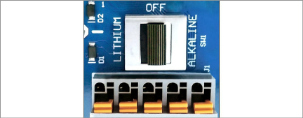
Figure 13: Battery Select Switch
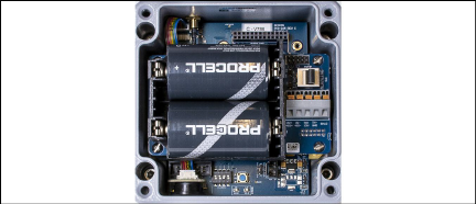
3. Install the batteries by aligning the positive (+) side of the D cells with the + indicator in the battery holder. Push the batteries straight down into the holder.
4.Move the battery select switch to either the Alkaline or Lithium position depending on the type of battery being used.
5.An LED will flash on the right side of the box indicating the unit has power.
To connect a sensor:
1.Open the device by unscrewing the four captive screws on the front of the enclosure. Ensure that no dirt, water or other contaminants are allowed to enter the enclosure.
2.Loosen the nut on the cable fitting and remove the white plastic dowel.
3.Slide the transducer cable through the cable gland nut and fitting.
4.Insert each conductor wire into the terminal block by pressing down on the orange tab, inserting the bare end of the conductor into the terminal block, and then releasing the tab. Refer to Figure 15 and Table 2 for sensor wiring information. To prevent the possibility of a short circuit, do not allow bare leads to touch each other during or after wiring.
|
Color |
Description |
|
|
VW+ |
RED |
Vibrating Wire + |
|
VW− |
BLACK |
Vibrating Wire − |
|
TH+ |
WHITE |
Thermistor + |
|
TH− |
GREEN |
Thermistor − |
|
SHD |
BARE |
Analog Ground (shield) |
table 2: Node Wiring
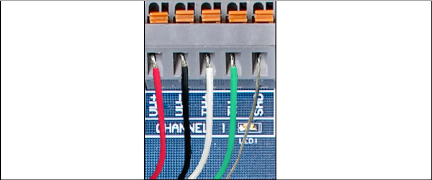
Figure 15: Terminal Connections
5.Pull gently on each conductor to ensure it is secure.
6.Tighten the cable gland nut until it firmly grips the outer jacket of the cable. The cable gland nut must be properly tightened to prevent water entry. Do not over-tighten, as this might strip the plastic threads.
7.Pull gently on the sensor cable to ensure it is held in place by the cable gland.
After the batteries have been installed, complete the following with the supervisor and the node units:
1.Place the supplied desiccant packs inside the enclosure.
2.Ensure the cover gasket and the mating ridge on the enclosure are clean, and that the gasket is properly seated inside the groove on the cover. Place the cover on the unit.
3.Tighten the cover screws a little at a time, working in a diagonal pattern. Make sure the cover seals tightly and evenly.
4.Mount the device. The built-in mounting plate is designed to be used with U-Bolts, hose clamps, screws, bolts, etc. Devices should be mounted vertically, with the antenna pointing up.
There are two modes of operation: Deployment mode and Normal mode. The supervisor and node units all enter Deployment mode upon power up or system reset. Perform a system reset by either pressing the blue Reset button on the GeoNet circuit board, or by pressing and holding the Status button on the side panel for 10 seconds.
For information on the function of the Status button, see Section 2.3.
Deployment mode allows nodes to be added to a network and verified quickly. When the network is in Deployment mode, the network status will be indicated by the LEDs on the supervisor every 10 seconds.
In Deployment mode, the supervisor and node units will find each other in less than three minutes, radio circumstances permitting. Once the network has been established and the network time has been set, the Supervisor's green LED will flash simultaneously with the green LEDs on the nodes. If the network time has not been set, the Supervisor's red LED will blink in unison with the nodes. The time must then be set using the Agent software.
If the correct lights do not illuminate, or if the network has exited Deployment mode, press the Status button on the supervisor to restart Deployment mode.
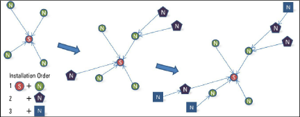
While in Deployment mode, nodes may be added by simply turning them on within radio range. When adding nodes, start with those closest to the supervisor. Place the supervisor in the center of the distribution of nodes if possible (see Figure 16 below); doing so will reduce the number of hops, which will reduce battery consumption.
Move nodes to their installation locations as long as the green LED is flashing. Pay attention to the LEDs while moving the nodes to ensure the signal isn’t lost.
After 10 minutes, the LEDs on the nodes will stop indicating their status in order to conserve batteries. Pressing the Status button on a node will reactivate the LEDs for another 10 minutes.
The default time a network will remain in Deployment mode is one hour. When a new node joins the network the timer will reset, extending the deployment period for another hour. If more time is needed while deploying nodes, the default deployment timeout may be changed using Agent software.
|
|
The network will not begin collecting data until the network |
If isolated from the rest of the network, a node will continue to sample and store data. When communication is reestablished, it will "catch up" by sending all of the collected data to the supervisor.
16:
2.3Status Button Functionality
All GeoNet devices have red and green LED indicators to display their status. A reference key is printed on the side of each unit, below the LEDs. When pressed, the Status button triggers the appropriate LED indicators to briefly illuminate. Table 3 shows the meaning of the various LED indications.
Note: When used in a sensemetrics network, see Section 7 for the meaning of the LED indications.
|
Supervisor |
Nodes |
||
|
|
|
Time set, nodes present |
GOOD: Radio signal > 30% |
|
|
|
Time set, no nodes present |
MARGINAL: Radio signal < 30% |
|
|
|
Network time not set |
BAD: No radio signal |


table 3: LED Indicator Meaning
When the Status button is pressed on the supervisor the current status of the network will be displayed briefly by the LEDs. If the network is in Deployment mode when the button is pressed, the Deployment mode timer will reset. If the network is not in Deployment mode, it will enter Deployment mode on the following radio cycle. This could take up to six minutes, as changes to the radio settings can only occur when all the radios in the network are awake. In order to provide timely feedback to the user, the network parameters are set to a 10-second radio interval while the supervisor is in Deployment mode.
When the Status button is pressed on a node, the current status of the radio signal will be displayed briefly by the LEDs. The node will then indicate the status of the radio signal after each radio transmission for a period of 10-minutes. If the node has not yet joined the network, it will change its radio interval to approximately one second and search for an available network.
Remember: Pressing and holding the Status button for 10 seconds on a Supervisor or Node will trigger a reset of the unit.