The GeoNet Multi-Channel Node (MCN) increases the number of sensors a node can read, as indicated in the following table.
|
Model |
Maximum Number of Sensors |
Maximum Number of Load Cells |
|
04C |
Four |
One |
|
08C |
Eight |
Two |
table 5: Multi-Channel Node Sensor/Load Limits
Channel switching is controlled by the node and is accomplished by solid-state (non-mechanical) circuitry.
Each MCN uses as much data as four or eight single nodes, depending on the node model. The MCN is protected from environmental contaminants by a rugged IP66 die cast aluminum enclosure. An earth ground terminal is provided on the exterior of the enclosure to protect against lightning and other large, transient voltages.
MCNs ship with the following accessories:
■One omnidirectional antenna (2.1 dBi). For other antenna options, please contact GEOKON technical support.
■Two D cell alkaline batteries
■Four desiccant packs
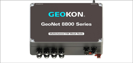
Figure 18: Multi-Channel Node, Eight Channel Node Shown
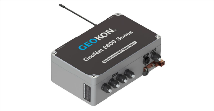
Figure 19: Multi-Channel Node Connectors; Four Channel Node Shown
Multi-channel sensor nodes function in the same manner as other nodes, and can be installed using the previous sections in the manual. However, the following information should be useful for installing these nodes.
4.1.1Mounting the Multi-Channel Node
The MCN must be mounted vertically, so that the antenna points up (as shown in Figure 18 above). Attach the MCN to the mounting surface using the MCN’s mounting plate. Mounting hardware is available for purchase from geokon.
Each vibrating wire (VW) channel is protected by a 230V gas discharge tube, followed by a high-speed surge protector and a transient voltage suppression diode. Each thermistor (TH) channel is protected by a 230V gas discharge tube, followed by an inductor (lower resistance than high-speed surge protectors) and a transient voltage suppression diode.
For these components to safely divert lightning energy to ground, a solid electrical connection to earth ground is required. A copper grounding rod at least six feet in length should be driven into the soil to a minimum depth of three feet, as close to the MCN as possible. Alternatively, any other suitable earth ground attachment may be used. Connect the grounding rod to the copper grounding lug on the exterior of the MCN (see Figure 19 above) with a 12 AWG or larger wire. This will provide a suitable path from the MCN to earth ground in the event of a lightning strike.
4.2.1Cable Gland Models (–CBL)
1.Open the MCN by loosening the four captive screws on the front of the enclosure and removing the lid. Ensure that no dirt, water, or other contaminants enter the enclosure.
20:
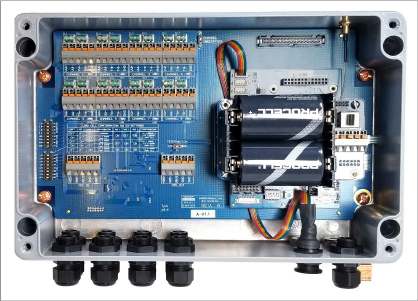
Figure 20: Multi-Channel Node Interior
2.Loosen the cable gland nuts and remove the white plastic dowels. To prevent contaminants from entering the enclosure, do not remove the dowels from cable fittings that will not be used.
3.Thread the transducer cables through the cable fittings. To simplify cable management inside the enclosure, wire transducer cables sequentially.
4.Insert the conductors of each cable into the terminal blocks of the MCN by pressing down on the orange tab at the back of the terminal block, inserting the conductor, and then releasing the orange tab. See Section 4.2.2 for information on determining the correct wiring.
5.Pull gently on each conductor to ensure it is secure.
6.Tighten the nuts on the cable fittings. This must be done to ensure that water does not enter the enclosure. Avoid overtightening as this may damage the plastic threads.
7.Pull gently on the sensor cable to ensure it is held in place by the cable gland.
8.Reinstall the cover. Ensure that the rubber gasket is properly seated in the groove on the underside of the cover. Tighten the screws a little at a time, working in a diagonal pattern; this ensures that the cover seals correctly.
4.2.2Determining Correct Wiring
geokon instruments with a single vibrating wire gauge should be wired as shown in the table below:
|
Position |
Color |
Description |
|
VW+ |
RED |
Vibrating Wire + |
|
VW− |
BLACK |
Vibrating Wire − |
|
TH+ |
WHITE |
Thermistor + |
|
TH− |
GREEN |
Thermistor − |
|
SHLD |
BARE |
Analog Ground (shield) |
table 6: Standard Single Gauge Wiring
To determine the correct wiring for geokon instruments with multiple vibrating wire gauges, refer to the wiring chart(s) in the manual provided with the instrument. These types of instruments will require the use of more than one channel in the MCN.
Supervisors, single channel nodes, and addressable nodes must be grounded through the mounting hardware for maximum protection.
An MCN can be added to a network at any time; it will be detected and used automatically if the network is already in deployment mode.
Note: geokon recommendeds that you connect sensors to the MCN before connecting the node to the network.