The geokon Solar Panel Kit enables you to power a Cellular Gateway Supervisor in an area that has no access to mains / domestic power.
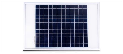
Figure 44: Solar Panel 8900-SOL-10W-BRJ
Inside the kit box are the following:
■One envelope containing technical documents and instructions
■One mounting bracket
■One solar panel complete with power regulation circuitry and power cable
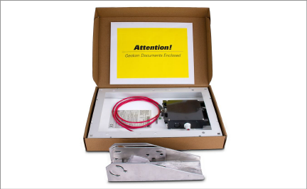
Figure 45: Solar Panel Kit Box Contents
Installation Overview
The general installation steps are as follows:
1.Select a location for the solar panel.
2.Assemble and adjust the mounting bracket to the proper angle.
3.Install the mounting bracket.
4.Secure the solar panel to the mounting bracket.
5.Connect the power cable to the Cellular Gateway Supervisor.
Choose a location for the solar panel that is clear of obstructions and anything that might cast a shadow on the panel.
F.2Assemble the Mounting Bracket
When assembling the two sections of the mounting bracket, be sure to set the sections to the desired angle before tightening the nuts. The angle of the mounting bracket will dictate the angle of the solar panel.
■Ensure the angle is at least 10 degrees, to aid in water control.
■In general, choose the best angle for the latitude of your location.
■Mounting on a horizontal surface will require a reverse configuration of the two sections compared to mounting vertically. See the figure below.

Figure 46: Mounting Options
F.3Install the Mounting Bracket
Mount the bracket on a flat surface (roof, wall, etc.) using locally-supplied bolts or lag screws. If mounting to a pole, use locally-supplied U-bolts and retaining clamps.
F.4Secure the Solar Panel to the Mounting Bracket
Use the included nuts and screws to secure the solar panel to the mounting bracket. Use the centrally-located holes provided for this purpose on the back of the solar panel.
Note: Be sure to mount the solar panel with the cable coming out the bottom of the panel, as shown below.
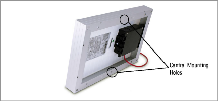
Figure 47: Centrally-Located Mounting Holes
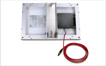
Figure 48: Mounting Bracket Fastened Centrally
Before connecting the power cable, be sure you have set the battery switch appropriately, as indicated in Section 3.2.2.
■When not using an external battery, set the battery switch inside the Supervisor to the battery setting.
■When using an external battery between the solar panel and the Cellular Gateway Supervisor, set the battery switch inside the Supervisor to the 9-24V setting.
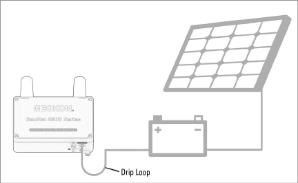
Figure 49: Solar Panel with External Battery
Remove the plastic cap from the cable connector, then attach it to the 9-24V plug on the Cellular Gateway Supervisor. Tighten the retaining ring on the 9-24V plug, for strain relief.
Note: Be sure to implement a drip loop, as indicated in the previous figure, to prevent water ingress through the power connector.