2.Initial Setup
The GK-404 is sold with the following accessories:
■GK-404-1 flying leads
■Carrying case
■Nylon strap for the carrying case
■Neck strap for the GK-404
Before use, attach the flying leads to the GK-404 as follows:
1.Align the red circle on the silver Lemo connector on the flying leads with the red line on the connector on the top of the GK-404.
2.Insert the Lemo connector into the GK-404 until it locks into place (see Figure 1).
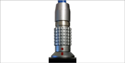
Figure 1: Lemo Connector to GK-404
3.Remove the flying leads before storing the GK-404 in the carrying case.
To connect the nylon strap to the carrying case, clip both ends of the strap onto the plastic loops on the sides of the case.
Connect the neck strap to the GK-404 as follows:
1.Locate the plastic connector on the neck strap (see the figure below).
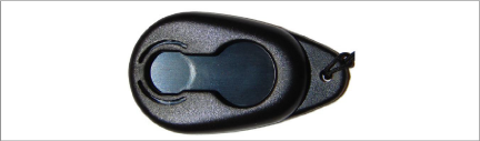
Figure 2: Neck Strap Connector
2.Place the larger circular hole onto the plastic nub on the back of the GK-404, with the bottom of the connector to the right (see the figure below).
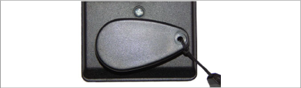
Figure 3: Connector on GK-404
3.Slide the connector all the way to the right, so that the nub on the back of the GK-404 locks into the smaller hole of the connector.
4.Turn the connector clockwise until the bottom of the connector is pointing down (see the figure below).
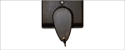
Figure 4: Downward-Pointing Connector
Snap together the twin connectors located at the strap ends (see the figure below).
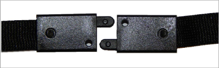
Figure 5: Neck Strap Connections
Attach the GK-404-1 flying leads to the bare leads of a geokon vibrating wire sensor by connecting each of the clips on the leads to the matching colors of the sensor conductors, with blue representing the bare shield wire.
geokon makes patch cables that enable the GK-404 to read sensors with connectors attached to the readout cable.
If a load cell cable has a readout cable connector attached, the GK-404 can easily connect to it using a patch cable provided by geokon.
If the load cell cable does not have a connector, the leads of the load cell may be connected directly to the flying leads from the GK-404. The individual leads can be identified as shown in the wiring diagram in Table 1 below.
Each sensor is read in turn by connecting either the red or black clip to the lead marked common. The black or red clip must be connected to the leads marked #1, #2, #3, etc. The blue clip should be connected to the cable shield wire, and the green and white clips to the cable leads marked thermistor.
|
10‑pin Bulkhead PT06A‑12‑10P |
Function |
Three Gauge VW Load Cell Geokon Purple Cable |
Four Gauge VW Load Cell Geokon Purple Cable |
Six Gauge VW Load Cell Geokon Orange Cable |
|
A |
Gauge #1 |
Red |
Red |
Red |
|
B |
Gauge #2 |
Red's Black |
Red's Black |
Red's Black |
|
C |
Gauge #3 |
White |
White |
White |
|
D |
Gauge #4 |
NC |
White's Black |
White's Black |
|
E |
Gauge #5 |
NC |
NC |
Green |
|
F |
Gauge #6 |
NC |
NC |
Green's Black |
|
G |
Shield |
All Shields |
All Shields |
All Shields |
|
H |
Common |
White's Black¹ |
Green |
Blue |
|
J |
Thermistor |
Green¹ |
Blue |
Yellow |
|
K |
Thermistor |
Green's Black |
Blue's Black |
Yellow's Black |
1 White's black and Green wires are switched on Geokon three gauge VW load cells prior to serial number 3313.
table 1: Load Cell Wiring Diagram