2.Installation
Prior to installation, check the sensors for proper operation. Complete the following steps:
1.Place the sensors in the correct order by referring to the labels on the sensors and the provided paperwork.
2.Starting with the first sensor, connect the sensors by plugging the male connector from the second sensor into the female connector from the first sensor. Proceed in this manner until the full string is connected.
1:
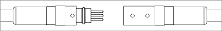
Figure 1: Cable Connection Detail
Caution! When connecting the sensors, make sure to line up the orientation dot on the outside of the male connector with the two orientation dots on the outside of the female connector. This will ensure the pins and receptacles on the interior of the connectors align correctly. Push the connectors together until they are completely mated.
2:

3.Connect the completed string to a Model 8020-38 converter, PC, or datalogger (refer to Section 2.6).
4.Hold the first sensor in a vertical position and observe the reading. The tilt sensor must be held steady while taking the reading. The observed reading should be close to the factory vertical reading. Tilting the sensor in a positive direction (A+ or B+, as marked on the sensor) should yield increasing readings. Tilting the sensor in a negative direction (A- or B-) should yield decreasing readings. The temperature indicated on the readout should be close to ambient. Repeat this process with the remaining sensors.
5.Once the preliminary tests are complete, disconnect the string from the readout device and disconnect the sensors from each other.
Should any of these preliminary tests fail, see Section 5 for troubleshooting.
geokon strongly recommends attaching a safety cable to the bottom-most (terminal) sensor, Model 6180T. This can be used to retrieve the assembly in the event of an accident, and it also can be helpful when lowering the assembly into the casing.
Model 6180-6 safety cable assemblies purchased from geokon consist of a customer-specified length of aircraft cable (07-125SS316-E/M) with eye bolt and hex nuts pre-attached for ease of installation, along with all hardware required to anchor the string.
To connect the safety cable to the terminal sensor, complete the following steps:
1.Fasten the upper end of the safety cable to a fixed object, or to something too large to enter the casing, to avoid accidentally dropping the entire cable into the casing.
2.Remove the two hex nuts from the eye bolt.
3.Insert the eye bolt through both connection holes on the terminal sensor.
4.Thread the two nuts back onto the bolt and tighten against one another using two 5/16" crescent wrenches; this will secure the safety cable to the terminal sensor.
The figure below shows a properly connected safety cable.
3:
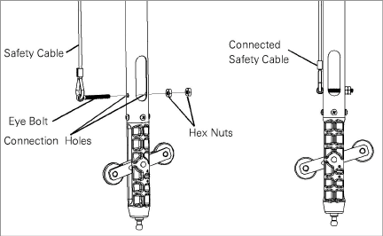
Figure 3: Connecting a Safety Cable
5.Tie off the top end of the safety cable by attaching it to an appropriate anchor point. Follow the procedure from Section 2.5.1 for proper installation of the cable clamps.
All wheel assemblies should be oriented in the same direction when installed in the casing. The wheel assemblies are attached at the factory so the upper wheel is facing the A+ direction of the sensor (as shown in the figure below). Axis directions are also physically labeled on each sensor.
4:

Point the A+ direction in the same direction as the anticipated movement, i.e., towards the excavation being monitored or downslope for slope evaluation applications.
The MEMS device monitors both A and B directions. The B+ direction is 90 degrees clockwise from the A+ direction, as viewed from above.
The first sensor to install is the Model 6180T terminal sensor, which includes two sets of wheels.
1.Insert the 6180T sensor into the casing, making sure to orient the wheels correctly for proper axis orientation (see Section 2.3), and with the male cable connector facing up toward the top of the casing.
2.With the safety cable attached, lower the first sensor into the casing hole, until the ¼" support holes are adjacent the top of the casing.
3.Suspend the sensor in place at the top of the casing by inserting a ¼" diameter screwdriver or rod through the support hole on the side of the sensor. Refer to the figures below.
5:
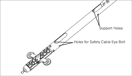
Figure 5: Holes for Safety Cable Eye Bolts vs Holes for Support Holes
6:

Figure 6: Support Sensor with Rod
2.4.2Connect the Second Sensor to the First Sensor
1.Each 6180 segment is supplied with a barbed locking pin pre-installed.
7:
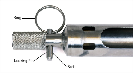
Figure 7: Pre-inserted Locking Pin
2.Remove the locking pin by depressing the barb and pulling the ring at the same time.
8:
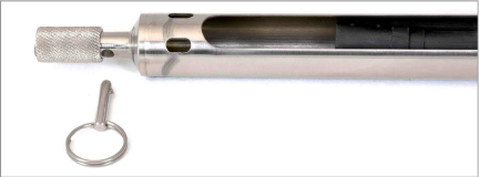
Figure 8: Remove the Locking Pin
3.Retract the spring sleeve on the second sensor and mate the ball stud of the first sensor to the receiver of the second sensor by connecting them together using a lateral motion.
9:
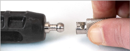
Figure 9: Retract the Spring Sleeve
4.Capture the ball stud by releasing the spring sleeve (make sure the sleeve returns to its initial position).
10:
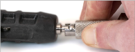
Figure 10: Capture the Ball Stud
5.Reinsert the locking pin to prevent the sleeve from retracting while in use.
11:
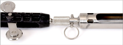
Figure 11: Completed Connection
6.Plug the male connector of the first sensor’s signal cable into the female connector of the second sensor’s signal cable.
Caution! When connecting the sensors, make sure to align the two orientation dots on the outside of the female connector with the orientation dot on the outside of the male connector. This will ensure the pins and receptacles on the interior of the connectors align correctly. Push the male and female connectors together until they are completely mated.
12:
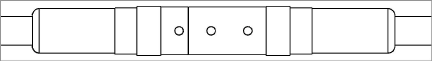
Figure 12: Cable Connection Detail
Note: For additional security, tape the connectors together.
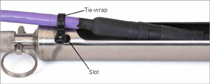
7.Using a provided tie wrap, secure the cable of the male connector to the tube of the second sensor by feeding the tie wrap through the parallel slots, around the cable, and back to itself; this will help provide strain relief for the connectors. Trim any length of excess tie wrap. See the figure below.
13:
8.Remove the screwdriver/rod from the first sensor and, with the safety cable attached, lower the second sensor into the casing hole, until the ¼" support holes are adjacent the top of the casing. Make sure to orient the A+ direction of each sensor correctly when inserting it into the casing.
9.Suspend the second sensor in place at the top of the casing by inserting a ¼" diameter screwdriver or rod through the the support hole on the side of the sensor.
10.Repeat steps 2 - 9 above for each subsequent sensor.
11.Plug the male connector of the top-most sensor to the female connector of the readout cable (6180-3-1, 6180-3-2, or 6180-3V). Connect the other end of the readout cable to the readout device or data-logger.
2.5Connecting the Suspension Bracket
To ensure the string is installed to the correct depth, sum the sensor lengths and subtract this value from the desired string depth (measured from the top of the casing to the bottom of the string assembly); the resulting value is the Suspension Cable Length.
Note: geokon suggests suspending the sensor string at least 150 mm (six inches) above the bottom of the casing, to account for debris and settlement.
2.5.1Connect the Cable Assembly to the Bracket
1.Hook the supplied thimble through the bottom-side eyelet on the suspension bracket (6180-2).
2.Feed the bare cable end of the suspension cable assembly (6180-1) through the bottom-side eyelet on the suspension bracket.
3.Pull the cable through the eyelet until the distance from the suspension bracket support shoulder to the end of the suspension receiver is equal to the previously calculated Suspension Cable Length.
4.Fold the "dead end" of the cable back onto the "live end", then secure one of the supplied cable clamps onto the cable at a distance of approximately 3.5 inches from the bottom-side eyelet on the suspension bracket. (Install the cable clamp nuts firmly, but not tighten them down yet).
5.Orient the cable clamp with the two ends of the U-bolt facing toward the "live end" of the cable as shown below.
14:

Figure 14: Attach the First Cable Clamp
6.Seat the loop formed by the cable into the channel of the thimble.
7.Install a second cable clamp onto the cable at the base of the thimble (see image below).
15:
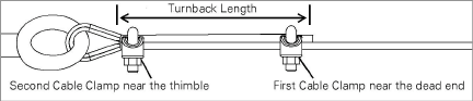
Figure 15: Attach the Second Cable Clamp
8.Adjust the first cable clamp so the "turnback length" measures approximately 3.25 inches.
9.Apply light tension to the cable to remove all slack. Tighten all four cable clamp nuts to a torque specification of approximately 4.5 ft-lbs.
10.If desired, the third supplied cable clamp may be installed in between the first and second cable clamps (make sure to tighten nuts to the previously mentioned torque specification).
11.Trim the excess cable from the "dead end", leaving at least 3/8 inch of length from the first cable clamp. Alternatively, wrap the end of the cable with tape and then tape it to the main length of the suspension cable.
16:
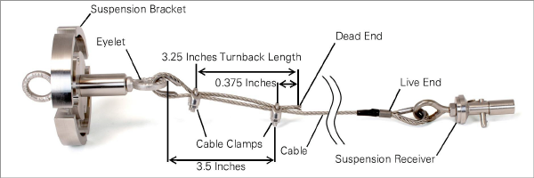
Figure 16: Assembled Suspension Cable (Example)
2.5.2Connect the Cable Assembly to the Sensor String
The suspension cable assembly attaches to the sensor string similar to how the sensors attach to each other. For illustrated steps refer to Section 2.4.2.
1.Remove the locking pin from the suspension receiver by depressing the barb and pulling the ring at the same time.
2.Retract the spring sleeve on the suspension receiver and mate the ball stud of the top-most sensor to the suspens0ion receiver by connecting them together using a lateral motion.
3.Release the spring sleeve to secure the ball stud inside the sleeve.
4.Reinsert the locking pin to prevent the sleeve from retracting while in use.
2.5.3Lower the Top-most Sensor
Lower the top-most sensor into the casing and position the suspension bracket on top of the casing.
Important! Ensure the top rim of the casing is relatively square to properly seat the suspension bracket.
Readings may be taken immediately after installation, however, geokon recommends evaluating the data over a period of time to determine when the string has sufficiently stabilized and when the zero readings should be established.
2.6Model 8020-38 RS-485 to TTL/USB Converter
geokon makes the Model 8020-38 Addressable Bus Converter for connecting addressable strings to personal computers, readouts, dataloggers, and programmable logic controllers. The converter acts as a bridge using the TTL or USB protocols between readers and the geokon RS-485-enabled sensor strings.
For more information, please refer to the Model 8020-38 instruction manual.
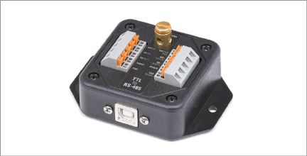
Figure 17: Model 8020-38 RS-485 to TTL/USB Converter
Note: The datalogger you use must have the appropriate port available.
18:

Figure 18: Wiring of Datalogger without built-in RS-485 Conversion
nIf your datalogger does not have built-in RS-485 communications, connect the wiring using the diagram below.
nIf your datalogger has built-in RS-485 communications, connect the wiring using the diagram in the figure below.
19:
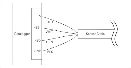
Figure 19: Wiring of Datalogger with built-in RS-485 Conversion
2.7Four-Pin Waterproof Connector
The pinouts for the four-pin male and female connectors are shown below; the function of each wire is detailed in Table 1 below.
20:
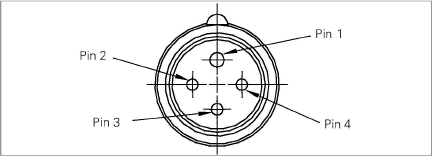
Figure 20: Male Waterproof Connector
21:
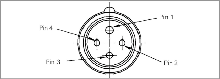
Figure 21: Female Waterproof Connector
|
Pin |
Wire Color |
Function |
|
1 |
Red |
Power |
|
2 |
Black |
Ground |
|
3 |
White |
RS-485+ Data High |
|
4 |
Green |
RS-485- Data Low |