Stressmeters are designed to be used in smooth-walled diamond drill holes. Stressmeters can be installed in percussively drilled holes and drag bit drilled holes, provided that care is taken to get the proper hole diameter with a smooth wall. If the walls are rough, the gauge response (calibration) can be radically affected.
Standard hole configurations:
Model 4300EX stressmeters are designed for use in EX diamond drill holes 38 mm (1.5"), and the hole can range in diameter from 37 mm (1.45") to 39 mm (1.55") when using the standard wedge and platen assembly.
Model 4300BX stressmeters are designed for use in BX diamond drill holes 60 mm (2.36"), and the hole can range in diameter from 59 mm (2.30") to 61 mm (2.40") when using the standard wedge and platen assembly.
Model 4300NX stressmeters are designed for use in NX diamond drill holes 76 mm (2.98"), and the hole can range in diameter from 75 mm (2.95") to 77.5 mm (3.05") when using the standard wedge and platen assembly. Oversize platens are available for oversize boreholes (consult factory).
After drilling, the hole should be thoroughly cleaned by washing out with water or blowing out with compressed air. The borehole diameter should then be checked using the GO / NO-GO gauges as follows:
Screw the "GO" gauge onto the section of ¼" rod that has a ¼-20 left-handed thread on one end by rotating it counterclockwise. (Note: All male ends of the ¼" rods have normal right-hand threaded connections except for the first section which has a left-hand thread.)
Push the "GO" gauge into the borehole.
Add a section of ¼" rod to the assembly by inserting the threaded male end into the female coupler and turning it clockwise.
Continue to add sections of ¼" rod while pushing the gauge into the borehole until the gauge reaches the desired depth of the stressmeter installation. If the borehole diameter is correct, the "GO" gauge will fit into the borehole all the way to the installation depth. If the "GO" gauge does not fit into the borehole, or does not reach the installation depth, the borehole is too small.
Remove the "GO" gauge from the borehole and unscrew it from the ¼" rod by turning it clockwise.
Screw the "NO-GO" gauge onto the ¼" rod by rotating it counterclockwise.
Attempt to push the "NO-GO" gauge into the borehole. If the borehole diameter is correct, the "NO-GO" gauge will not fit in the borehole at the intended installation depth. If the "NO-GO" gauge does fit into the borehole, the borehole diameter is too large.
Remove the "NO-GO" gauge from the borehole and unscrew it from the ¼" rod by turning it clockwise.
If the borehole did not pass the above tests rework it as needed.
Repeat the steps above until the borehole is sized correctly.
Before installing the gauges in the field, perform a preliminary check by completing the following
1.Connect the gauge to a readout box. See Section 3 for more information.
2.Take a reading. Zero readings at the site should coincide with the factory readings within a few digits after corrections for temperature are made. See Section 4.4 for information on temperature correction.
3.Use an ohmmeter to check electrical continuity. The resistance between the two lead wires (usually red and black) should be about 180 ohms for BX and NX models, and 90 ohms for EX model. Remember to add the cable resistance at approximately 14.7Ω/1000' (48.5Ω/km) at 20 °C. Multiply this factor by two to account for both directions.
4.Using an ohmmeter check the resistance between the two thermistor wires (usually white and green). Using Table 3, convert the resistance to temperature. Compare the result to the current ambient temperature.
2.3Attaching the Wedge/Platen Assembly
The wedge/platen assemblies are shipped separately. They are held together by a nylon screw and nut. Do the following:
1.Remove the nut and then use the nylon screw to attach the wedge/platen assembly to the stressmeter body.
2.Orient the wedge so that the narrow end is facing in the same direction as the cable, as displayed in the figure below.
2:
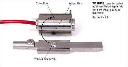
Figure 2: Stressmeter with Wedge, Screw and Nut
3.Tighten the nylon screw into the threaded hole in the body. Do not overtighten the screw as it may break; it is made of nylon so that it can be sheared easily later in the installation.
Note: Both the BX and NX stressmeters use the same wedge. There are two holes in the wedge: the one nearest the tip is for the BX model, the one farthest from the tip is for the NX model.
2.4Protecting the Sealant Holes
The sealant holes on EX models are filled with a sealant that makes the interior watertight. Take care not to disturb this sealant: doing so risks allowing water to penetrate the interior, which can render the stressmeter inoperable.
Note: The BX and NX models feature a metal cap welded over the sealant holes.
2.5Setting the Stressmeter (Recoverable Type)
Mount the stressmeter to the setting tool by pushing the threaded nylon pins on the stressmeter into the matching holes in the setting tool head. Push straight in with moderate force. Make sure the pins are inserted fully so that no gap exists between the stressmeter and the setting tool.
Feed the gauge leads through the slot in the setting head.
Connect the first section of ¼" with a ¼-20 left hand thread on one end to the "yoke" located on the thin end of the wedge by turning the rod counterclockwise.
Attach the first section of the ¾" positioning rod to the back of the setting tool head. Push the stressmeter into the hole using the positioning rod. The buttons on the setting rod connectors indicated the orientation of the wedge/ platen assembly, e.g., for taking measurements in a vertical direction, keep the buttons to the top of the rod.
As the ¾" positioning rod is pushed into the hole, add new sections of both ¾" and ¼" rod until the desired depth has been reached.
Caution: Wear gloves during this procedure to protect the thumb while depressing the buttons on the ¾" rods.
Slide the slide-hammer over the last section of ¼" rod and then thread the anvil block onto the outer end of the ¼" rod. Connect the readout box to the lead wires and take initial readings. Refer to Section 3 for more information.
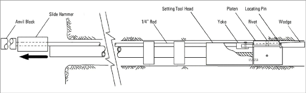
Figure 3: Vibrating Wire Stressmeter Installation Tool Assembly
Holding the positioning rod firmly at its correct depth and orientation, slide the slide-hammer back up the ¼" rod, then side it quickly back to the anvil striking it a sharp firm blow. This will shear the rivet holding the wedge to the platen and will pull the wedge into the platen thereby expanding it against the wall of the borehole.
After the first blow, take another reading on the readout box and observe the change in reading. The recommended preloads are as follows: For the EX size a reading change of 2000 digits on channel F, for the BX size a reading change of 400 digits on channel B, for the NX size a reading change of 200 digits on channel B. (Note that the stressmeter initial readings will probably diminish slightly over the first day or two as the instrument beds firmly into place.)
Use as many blows of the hammer as is necessary to achieve this reading. Stop hammering when successive blows produce little or no change of reading. Continued hammering can break the wedge! When the target reading has been achieved, or if successive hammer blows produce little or no change, disconnect the ¼" rod from the wedge yoke by turning clockwise. Remove the ¼" rod from the hole, and then disengage the setting tool from the stressmeter by pulling on it.
For multiple installations of gauges in a single hole, route the lead wires from deeper gauges through the recess in the side of the setting tool head. Maintain tension on these wires as subsequent gauges are pushed into the hole.
If necessary, after setting the gauges and obtaining the final readings, push the leads back into the borehole and seal the borehole using an expandable rockbolt anchor or a short bolt. This will discourage vandalism if this is a problem.
After tests, the stressmeter can be removed from the borehole by using the setting tool.
Only the larger setting rods are required, along with the setting tool head, which is used to strike the outer tip of the wedge. This will drive the wedge out from under the platen and allow the stressmeter to be pulled from the hole using the electrical cable. Make sure that the setting head is oriented so that the flat part of the front face lies opposite the wedge. The entire stressmeter can sometimes be recovered in this way i.e., the wedge, platen, and stressmeter body.
In order to reuse the stressmeter it will require a new nylon screw. (A few spare nylon screws are included in each shipment). However, there is a good chance that the wedge and platen may dislodge in the borehole and be lost; therefore, it is advised to order spares of these also.
Note: The BX size stressmeter and the NX size stress meter both use the same wedge. However, there are two holes in the wedge. The one nearest the tip is for the BX size; the one farthest from the tip is for the NX size.
2.7Splicing and Junction Boxes
Because the vibrating wire output signal is a frequency rather than a current or voltage, variations in cable resistance have little effect on gauge readings. Therefore, splicing of cables has no effect, and in some cases may in fact be beneficial. For example, if multiple stressmeters are installed in a borehole, and the distance from the borehole to the terminal box or datalogger is great, a splice (or junction box) could be made to connect the individual cables to a single multi-conductor cable. This multi-conductor cable would then be run to the readout station. For these types of installations, it is recommended that the stressmeter be supplied with enough cable to reach the installation depth, plus extra cable to pass through drilling equipment (rods, casing, etc.).
Cable used for making splices should be a high-quality twisted pair type, with 100% shielding and an integral shield drain wire. When splicing, it is very important that the shield drain wires be spliced together. Splice kits recommended by geokon incorporate casts that are placed around the splice and then filled with epoxy to waterproof the connections. When properly made, this type of splice is equal or superior to the cable in strength and electrical properties. Contact geokon for splicing materials and additional cable splicing instructions.
Junction boxes and terminal boxes are available from geokon for all types of applications. In addition, portable readouts and dataloggers are also available. Contact geokon for specific application information.