Appendix E.Model 4420-3 Low Profile Crackmeter
geokon Model 4420-3 low profile vibrating wire crackmeters use a Model 4150 strain gauge mounted to the underside of a stainless steel plate, an adjustable oval point set screw, and an instrument cable, which is secured and weatherproofed by a Swagelok connector.
The gauge is mounted as a cantilever, with the cable end of the crackmeter fixed to the mounting surface by a cap screw installed into an expansion anchor, with the opposite end left free. This free end allows the cone point set screw to maintain contact with the mounting surface (or reference disc) as it moves.
Strains are measured using the vibrating wire principle. As the mounting surface rises or falls, it increases or decreases the strain in the vibrating wire inside the 4150 gauge. This change in tension is measured as a change in the resonant frequency of vibration of the wire.
The threaded rod and accompanying jam nuts allow the zero reading to be adjusted as needed.
17:
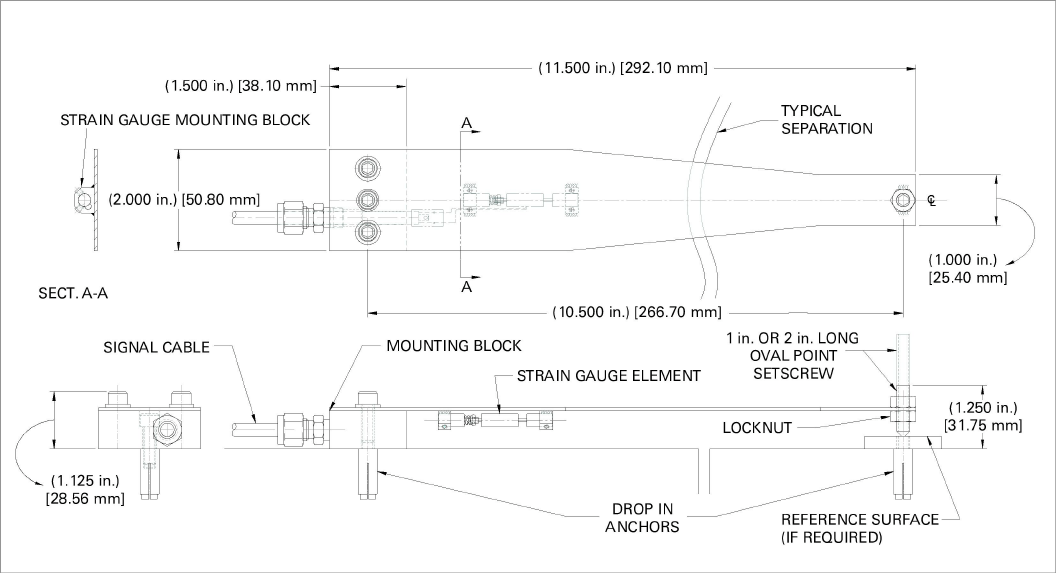
Figure 17: Model 4420-3 VW Low Profile Crackmeter Layout
Perform a preliminary check by completing the following:
1.Connect the gauge to a readout box using the instructions in Section 4.1.
2.Observe the displayed readout, which usually will be between 1800 and 2500 digits. The temperature reading should match the ambient temperature.
Checks of electrical continuity can be made using an ohmmeter. Resistance between the gauge leads should be approximately 50 ohms. Remember to add cable resistance, which is approximately 14.7Ω per 1000 feet (48.5Ω per km) of 22 AWG stranded copper leads at 20 °C. Multiply this factor by two to account for both directions. Resistance between the green and white conductors will vary based on temperature; see Table 7 in Appendix B. Resistance between any conductor and the shield should exceed two megohms.
Should any of these preliminary tests fail, see Section 6 for troubleshooting.
1.Using a masonry drill (or other suitable equipment), drill a 3/8" (9.5 mm) diameter x 1.25" (32 mm) deep hole on each side of the crack, at a spacing of 10.5" (267 mm).
Note: For mounting surfaces that are smooth in texture, the reference disc may be omitted. For installations without the reference disc only one hole and one expansion anchor is required. The completed assembly without a reference disc is shown in Figure 18 below.
2.Clean out the drill cuttings and insert the anchors into the holes, slotted end down.
3.Insert the provided setting tool, small end first, into each anchor. Expand the anchors by hitting the large end of the setting tool with several sharp hammer blows.
4.Using Loctite cement on the threads, screw the reference disc into one of the threaded expansion anchor holes until it is tight in the anchor.
5.Loosen the jam nuts on the oval point set screw. Using the wrench provided, back off the set screw so that it will not make contact with the reference surface when the gauge is mounted.
Note: A one-inch set screw is provided for installations where 75% or more of the displacement is anticipated to move the reference surface up in relationship to the crackmeter. When using the one-inch set screw, the jam nuts should be placed on the underside of the gauge, space permitting.
6.Align the threaded hole on the cable side of the crackmeter over the other anchor.
7.Slide a washer over the supplied cap screw and tighten it into the expansion anchor.
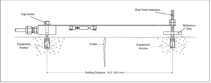
Figure 18: Crackmeter assembly using reference disk and two anchors
19:
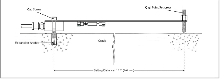
Figure 19: Crackmeter assembly with only one anchor and without a reference disk
8.Connect the cable to the readout box. Use the POS button to choose position E and the MODE button to select microstrain (µε). The calibration sheet indicates the minimum and maximum readings recommended based on the setpoints utilized during the calibration process.
9.Set the zero position by turning the oval point set screw until the desired reading is achieved. The correct zero reading can be determined by the following:
■If the set screw end of the gauge is anticipated to move up only in relationship to the 4150 gauge, set the zero reading near the 0.0 mm displacement according to the calibration sheet (about 2000 digits).
■If the set screw end of the gauge is anticipated to only move down in relationship to the 4150 gauge, set the zero reading near the 25.4 mm displacement according to the calibration sheet (about 12,000 digits).
■For unknown movement or to set the gauge at midrange, set the zero reading between the 10.2 mm and 15.2 mm displacement according to the calibration sheet (about 7000 digits).
Note: The above zero reading suggestions are given assuming the two sides of the joint are on the same plane when the instrument is installed. If there is a major discrepancy between the two sides, contact geokon to determine if a custom solution is required.
10.Once the reading is set, tighten the locknuts to secure the set screw.
11.In areas of high traffic, the gauge should be protected by a cover plate. For more information, see Section 3.2.
The table below lists the specifications.
|
Range: |
3000 µε |
|
Resolution¹ |
0.4 µε |
|
Calibration Accuracy |
0.1% FS |
|
System Accuracy2 |
2.0% FS |
|
Stability: |
0.1% / yr |
|
Linearity: |
2.0% FSR |
|
Thermal Coefficient |
12.2 µε/°C |
|
Temperature Range: |
-20 to +80 °C |
|
Readout Position |
E |
|
Display Units |
microstrain (µε) |
|
Frequency Range: |
1400-3500 Hz |
|
Coil Resistance: |
+50Ω |
|
Dimensions (gauge) |
57.2 x 6.4 mm |
|
Dimensions (coil) |
19.1 x 6.4 mm (diameter) |
|
Mid-Range Reading |
2500 µε |
|
Minimum Reading |
1000 µε |
|
Maximum Reading |
4000 µε |
table 11: Model 4420-3 Crackmeter Specifications
Notes:
1 Depends on the readout, above figure pertains to the GK-404 Readout.
2 System Accuracy takes into account hysteresis, nonlinearity, misalignment, batch factor variations, and other aspects of the actual measurement program. System Accuracy to 1.0% FS may be achieved through individual calibration of each crackmeter.
Range: -80 to +150 °C
Accuracy: ±0.5 °C
E.4Temperature Correction Factor
A small correction can be made for change in temperature. As the temperature goes up the average reading of the sensor will go down approximately one digit per °C. To calculate the displacement, corrected for temperature, use the equation below.
Dcorrected = G [(R1 – R0) + (T1 – T0)]
equation 8: Displacement, Corrected for Temperature
The temperature effect shown above is for a low profile crackmeter that has not been installed yet and is very minor. The actual temperature effect of the installed instrument can be arrived at empirically only by simultaneous measurements of deformation and temperature over a short period of time.