Prior to installation, check the sensors for proper operation. Complete the following steps:
1.Place the sensors in the correct order by referring to the labels on the sensors and the provided paperwork.
2.Connect the sensors by plugging the cable exiting the underside of one sensor into the cable exiting the top of the next sensor.
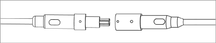
Figure 2: Cable Connection Detail
Caution! When connecting the sensors, make sure to line up the two nubs on the outside of the female connector with the nub on the outside of the male connector. This will ensure that the pins and holes on the interior of the connectors align correctly. Push the male and female connectors together until they are completely mated.

3.Once all sensors have been connected, plug the end terminator into the female connector at the bottom sensor. See the figure below.

Figure 4: End Terminator Model 6150F-2
4.Connect the completed string to a readout or datalogger.
5.Hold the first sensor in a vertical position and observe the reading. The tilt sensor must be held steady while taking the reading. The observed reading should be close to the factory vertical reading. Tilts in a positive direction (A+ or B+, as marked on the sensor) should yield increasing readings. Tilts in a negative direction (A- or B-) should yield decreasing readings. The temperature indicated on the readout should be close to ambient. Repeat this process with the remaining sensors.
6.Once the preliminary tests are complete, disconnect the string from the readout.
7.Disconnect all of the sensor cables. (The end terminator may remain on the bottom sensor.)
Should any of these preliminary tests fail, see Section 5 for troubleshooting.
2.2.1Assembling Using with Spacer Tubes
Each tilt sensor is supplied with fasteners attached, and with a connecting tube unattached. To complete the assembly of each segment, do the following:
1.Remove the nut/bolt fasteners from the sensor.
2.Connect the spacer tube to the connector at the bottom of the sensor.
3.Fasten the tube to the sensor using the nuts/bolts removed in step 1.
4.Repeat steps 1-3 for each sensor/spacer tube set.
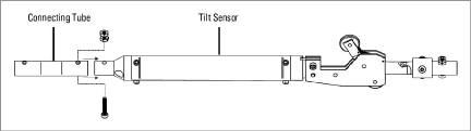
Figure 5: Connect the Segment Assembly
PLEASE NOTE:
□The one-inch cap screws used in the assembly procedure are installed in the connecting tubes at the factory and must be removed before attaching the tubing.
□The string will ship with a few spare cap screws and nuts. The shorter 3/8" cap screws are spares for the screws that attach the wheel assemblies.
□Where the spacing of the sensors is too long for a continuous length of tubing, connect two tubes together using the 6300-7 Tube Coupling (see the figure below). Use the one-inch cap screws and nuts to secure this connection.
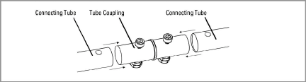
Figure 6: 6300-7 Tube Coupling
□Use Loctite 222 thread locking compound on all threaded connections.
Each tilt sensor is supplied with fasteners attached. To complete the assembly of each segment, do the following:
1.Remove the nut and bolt fasteners from the sensor.
2.Connect a wheel assembly to the top of the sensor.
3.Connect a wheel assembly to the bottom of the sensor.
4.Repeat steps 1-3 for each sensor.
5.Connect the sensors together by attaching a cable to the eyehooks on adjacent sensors.

Figure 7: Cable Connecting Segments
The bottom wheel assembly, Model 6300-5, has no universal joint, only a swivel. Attach this wheel assembly to the bottom segment using the provided hardware.
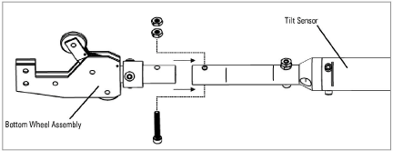
Figure 8: Connect the Bottom Wheel Assembly
Note: Remember to use Loctite 222 on all threaded connections.
Attaching a safety cable to the bottom wheel assembly is strongly recommended. Not only can it be used to retrieve the assembly if one of the joints breaks loose, but it is also very helpful when lowering the assembly into the casing.
Safety cables purchased from geokon will have an eye bolt on one end. Slide the eye bolt onto the 10-32 cap screw used to attach the bottom segment to the bottom wheel assembly. Tighten another nut onto the cap screw; this will trap the safety cable between the two nuts. The completed bottom wheel assembly is shown in the figure below.

Figure 9: Connect the Safety Cable
All wheel assemblies should be oriented in the same direction when installed in the casing. The wheel assemblies are attached at the factory so that the fixed wheel is facing the A+ direction of the sensor (as shown in the figure below).

It is customary and recommended to point the A+ (fixed wheel) direction in the same direction as the anticipated movement, i.e., towards the excavation being monitored or downslope for slope stability applications.
A second MEMS device is included in the sensor and is attached with its positive direction 90° clockwise from the first device. This is the B+ direction of the sensor.
1.Insert the bottom wheel assembly into the casing, making sure to orient the fixed wheel correctly (see Section 2.2.4).
2.Using the safety cable, lower the bottom segment into the casing hole, until the bottom sensor is at the top of the casing.
3.Hold the segment in place at the top of the casing using vice-grips or a similar method.
4.Plug the male connector of the bottom sensor into the female connector of the sensor above it.
Caution! When connecting the sensors, make sure to align the two nubs on the outside of the female connector with the nub on the outside of the male connector. This will ensure that the pins and holes on the interior of the connectors align correctly. Push the male and female connectors together until they are completely mated.
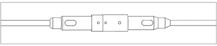
Figure 11: Cable Connection Detail
5.Tape the signal cable to the tubing, if desired. The connectors may be taped together for additional security.
6.Using the safety cable, lower the bottom segment into the hole, until the next sensor is at the top of the casing. Make sure to orient the A+ direction of the sensor correctly when inserting it into the casing.
7.Continue to add segments to the string. Connect the sensor cables together and lower the string into the casing, until the uppermost sensor is aligned with the top of the casing.
2.2.6Connecting the Suspension Bracket
Attach the suspension bracket to the top sensor’s wheel assembly via one of two methods: use a cable (sold separately), or use the connector tube provided.
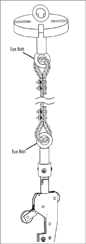
Figure 12: Suspension via Cable
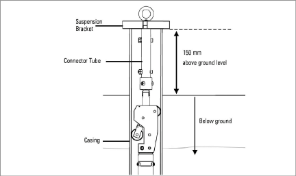
Figure 13: Suspension via Tube
Lower the final sensor into the casing and position the suspension bracket on top of the casing. It is important that the top rim of the casing be relatively square to prevent any side interference with the wheel assembly of the top sensor.
The safety cable can now be tied off at the top of the casing and the signal cable can be run to the readout location. Readings can be taken immediately after installation, but it is recommended that the system be allowed to stabilize for a few hours before recording the zero readings.
2.3Model 8020-38 RS-485 to TTL/USB Converter
geokon makes the Model 8020-38 Addressable Bus Converter for connecting addressable strings to personal computers, readouts, dataloggers, and programmable logic controllers. The converter acts as a bridge using the TTL or USB protocols between readers and the geokon RS-485-enabled sensor strings.
For more information, please refer to the Model 8020-38 instruction manual.
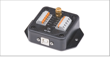
Figure 14: Model 8020-38 RS-485 to TTL/USB Converter
Note: The datalogger you use must have the appropriate port available.
■If your datalogger does not have built-in RS-485 communications, connect the wiring using the diagram below.
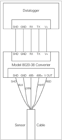
Figure 15: Wiring of Datalogger without built-in RS-485 Conversion
■If your datalogger has built-in RS-485 communications, connect the wiring using the diagram in the figure below.
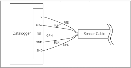
Figure 16: Wiring of Datalogger with built-in RS-485 Conversion
2.4Six-Pin Waterproof Connector
The pinouts for the six-pin male and female connectors are shown below; the function of each wire is detailed in Table 1 below.
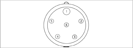
Figure 17: Male Waterproof Connector

Figure 18: Female Waterproof Connector
|
Pin |
Wire Color |
Function |
|
1 |
Red |
Power |
|
2 |
Black |
Ground |
|
3 |
White |
RS-485+ Data High |
|
4 |
Green |
RS-485- Data Low |
|
5 |
Bare |
Shield Drain |
|
6 |
N/C |
N/C |