Monitoring crack movements in three dimensions requires an array of three 4420 crackmeters, one each for monitoring the X, Y, and Z dimensions.
13:
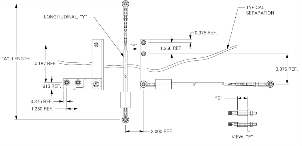
Figure 13: Typical 3D Array - Top View
14:
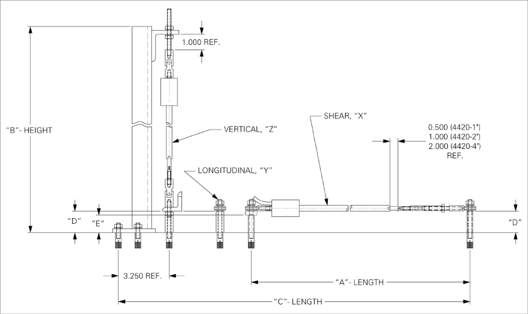
Figure 14: Typical 3D Array - Front View
|
Range |
'A' Length @ Midrange |
'B' Height |
'C' Length |
'D' Dimension |
'E' Dimension |
|
25 mm (1") |
342.90 mm (13.50") |
384.56 mm (15.14") |
558.80 mm |
34.93 mm |
28.58 mm |
|
50 mm (2") |
396 mm (15.625") |
489.28 mm (19.263") |
612.78 mm (24.125") |
60.33 mm |
53.98 mm |
|
100 mm (4") |
554.81 mm (21.843") |
701.88 mm (27.633") |
770.71 mm (30.343") |
111.13 mm (4.375") |
104.78 mm (4.125") |
table 9: 3D Array, Typical Version
The ends of the crack meters are fixed on each side of a fissure by means of a bracket or by direct mounting using expansion anchors.
Anchor Spacing
For spacing distances, refer to Table 1 in Section 2.2.1. When setting the gauge position using a portable readout, refer to Table 1 in Section 2.2.1 to determine the proper position.
X-Axis
The X-axis, as shown above, uses a 1/4" x 3/4" stainless steel bar to transfer parallel motion along the axis of the crack. This sensor requires two holes about 32 mm (1.25") apart, both 10 mm (3/8") in diameter and 32 mm deep. The holes must be perpendicular to the crack, and about an inch or two away. Once the anchors are installed with the spacers on top, attach the 5-5/8" long stainless steel bar using the provided threaded rods, lock washers, and nuts.
Note: The spacers used here are 1/8" shorter to accept the width of the bar. The spacing, chosen from Table 1 in Section 2.2.1, is then measured perpendicular from the 1/4-20 tapped hole in the stainless steel bar. Install another expansion anchor and spacer at this location, then attach the crackmeter with rod end bearings using the threaded rod, lock washer, and nuts provided.
Perform the following installation steps:
1.Using a masonry drill (or other suitable equipment), drill two 3/8 inch (10 mm) diameter holes, 1.25" (32 mm) deep, 1.25" apart. The holes should be positioned perpendicular to, and one-two inches in from, the crack.
2.Insert an expansion anchor into each of the holes, slotted end down.
3.Insert the provided setting tool, small end first, into the anchors. Expand each anchor by hitting the large end of the setting tool with several sharp hammer blows.
4.Remove the PVC slotted sleeve or dowel pin securing the transducer shaft.
5.Place the spacers on top of the anchors and attach the 5.625" long stainless steel bar to the anchors using the provided threaded rods, lock washers, and nuts.
Note: The spacers used here are 1/8" (3.2 mm) shorter than the others to accommodate the width of the bar.
6.Drill another 3/8" (10 mm) diameter, 1.25" (32 mm) deep holes, one directly below the 1/4-20 tapped hole in the stainless steel bar.
7.Using the spacing from Table 1 in Section 2.2.1, make another 3/8" (10 mm) diameter, 1.25" (32 mm) deep hole perpendicular from the one made in the previous step.
8.Insert expansion anchors into the holes created in steps five and six with the slotted ends down.
9.Place the spacers on top of the anchors and attach the crackmeter that has rod end bearings to the anchors using the threaded rod, lock washer, and nuts provided.
Y-Axis
The Y-axis monitors any movement perpendicular to the crack. It is mounted the same way in as the standard crackmeter installation, referenced in Section 2.2.4, with 3/8" diameter x 1 1/4" deep holes on each side of the crack, and at a spacing chosen from Table 1 in Section 2.2.1. Custom spacers are provided to be installed between the expansion anchors and the rod end bearings.
Perform the following installation steps:
1.Determine the proper setting distance using Table 1 in Section 2.2.1.
2.Using a masonry drill (or other suitable equipment), drill two 3/8 inch (10 mm) diameter holes, 1.25" (32 mm) deep at the proper locations.
3.Insert the expansion anchors into the holes, slotted end down.
4.Insert the provided setting tool into the anchor, small end first. Expand the anchor by hitting the large end of the setting tool with several sharp hammer blows.
5.Remove the PVC slotted sleeve or dowel pin securing the transducer shaft.
6.Push the cap screws through the swivel bearings and spacers on each end of the crackmeter and then tighten the cap screws into the anchors.
7.Check and record the reading with a portable readout.
Z-Axis
The Z-axis, as shown above, measures vertical movement along the crack utilizing two brackets: one to transfer movement across the crack, and one to mount the sensor vertically. The 5-5/8" long stainless steel angle iron is mounted across the crack by installing an expansion anchor with a spacer approximately two inches from the break. The vertical element is then aligned so that a crackmeter with U-joints on both ends will be upright in relation to the break. Two expansion anchors are supplied with this part located 1-1/4" apart, and no spacers are required. A percentage of the transducer’s range can be established by tightening or loosening the nuts on the long threaded rod.
The actual height of the crackmeters above the surface is determined by the spacers and is proportional to the range of the sensor, to accommodate the maximum amount of movement.
The 3D hardware comes standard with expansion anchors, but is designed to be interchangeable with groutable anchors.
For installation steps, refer to the instructions in Section 2.2.3 for groutable anchors and Section 2.2.4 for drop-in expansion anchors.
D.3Model 4420-3 Cantilever 3D Array Alternative
You can use the Model 4420-3 cantilever crackmeter to construct an alternative version of this 3D array, where the 4420-3 monitors the vertical Z-axis in a cantilever arrangement.
The 4420-3 employs a Model 4150 strain gauge to measure vertical movements. This version, shown below, is available in a one-inch range only.
15:
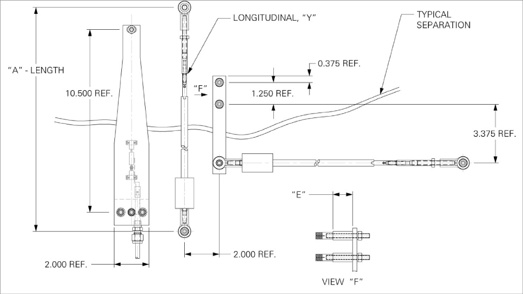
Figure 15: Cantilever 3D Array - Top View
16:
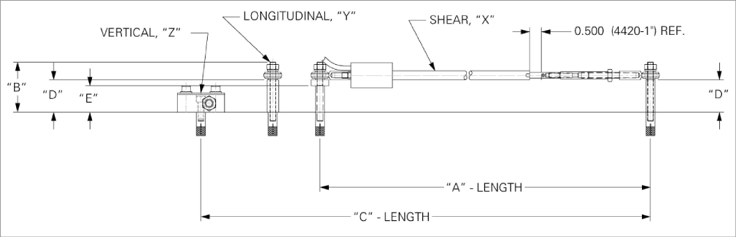
Figure 16: Cantilever 3D Array - Front View
|
Range |
'A' Length @ Midrange |
'B' Height |
'C' Length |
'D' Dimension |
'E' Dimension |
|
25 mm (1") |
342.90 mm (13.50") |
53.98 mm (2.125") |
558.80 mm (22") |
34.93 mm (1.375") |
28.58 mm (1.125") |
table 10: 3D Array, Cantilever Version
For detailed information about the 4420-3 low profile crackmeter, refer to Appendix E.