2.Installation
Check the gauge for proper operation when you receive it. Check the thermistor as well. The crackmeter normally arrives with its shaft secured at approximately 50% of its range.
For crackmeters with a range of 100 mm (4") or smaller, the shaft is secured using a dowel pin held in place by a piece of tape (see Figure 2).
For crackmeters with a range greater than 100 mm, a slotted sleeve made of PVC secures the shaft.
These devices hold the crackmeter in tension to protect it during shipping. With the shipping spacers still in place, connect the gauge to a readout box and take a reading. (See Section 4.1 for readout instructions.) The reading should be stable and in the range of 4000 to 5000 digits. Please note that crackmeters with a 3 mm (.125") range are shipped with the push rod fully retracted and have no shipping spacer to remove. These gauges should read between 2000 to 3000 digits.
Check electrical continuity using an ohmmeter. Be sure to consider the following:
■Resistance between the gauge leads should be approximately 180 ohms, ±10 ohms (128 ohms for the Model 4420HT).
■Remember to add the cable resistance, which is approximately 14.7Ω per 1000 ft. (48.5Ω per km) of 22 AWG stranded copper leads at 20 °C.
■Multiply this factor by two to account for both directions.
■Resistance between the green and white conductors will vary based on temperature.
■For standard crackmeters, refer to Table 7 in Appendix B.
■For the 4420HT crackmeter, refer to Table 8 in Appendix C.
■Resistance between any conductor and the shield should exceed two megohms.
Carefully remove the PVC slotted sleeve or dowel pin before proceeding further. Hold the transducer shaft to prevent it from snapping into the transducer housing.
For additional instructions Models 4420HT and 4420-3, see Appendix C and Appendix E respectively. For additional instructions regarding 3D Arrays, see Appendix D.
Three types of anchors are available:
■Weldable Mounting Fixture
■Expansion Anchor
■Groutable Anchor
The weldable fixture is designed to aid in mounting the crackmeter on steel members. The machine bolt expansion anchors and groutable anchors are used to install the crackmeter on concrete or rock. The anchors are installed at the appropriate spacing distance, depending on the anticipated direction of movement (extension or compression). Refer to the table below.
3:
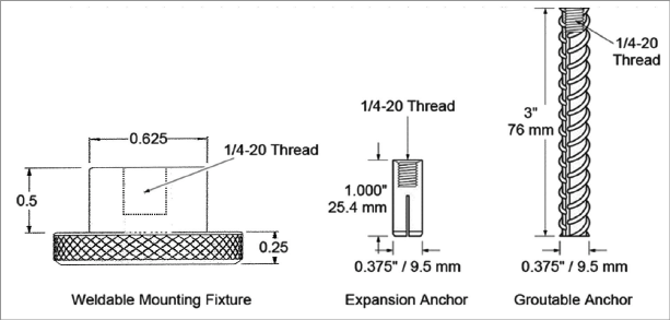
Figure 3: Anchor Types with Dimensions
Section 2.2.2 through Section 2.2.4 contain detailed instructions on each type of anchor. Section 2.3 contains special instructions on the following models:
■4420-1-3 mm (.125")
■4420-1-12.5 mm (.5")
■4420-1-25 mm (1")
|
Midrange |
To Monitor Extension |
To Monitor Compression |
|
|
4420-3 mm (.125") |
292.6 mm (11.52") |
291.1 mm (11.46") |
294.1 mm (11.58") |
|
4420-12.5 mm (.5") |
317 mm (12.5") |
310 mm (12.2") |
325 mm (12.8") |
|
4420-25 mm (1") |
343 mm (13.5") |
330 mm (13") |
356 mm (14") |
|
4420-50 mm (2") |
396 mm (15.6") |
371 mm (14.6") |
422 mm (16.6") |
|
4420-100 mm (4") |
554 mm (21.8") |
503 mm (19.8") |
605 mm (23.8") |
|
4420-150 mm (6") |
645 mm (25.4") |
569 mm (22.4") |
721 mm (28.4") |
|
4420-200 mm (8") |
869 mm (34.2") |
767 mm (30.2") |
970 mm (38.2") |
|
4420-300 mm (12") |
1186 mm (46.7") |
1034 mm (40.7") |
1339 mm (52.7") |
|
Note for Model 4420HT: Due to the U-joint configuration of 4420HT, the overall gauge assembly length is increased by 35 mm (1.375"). This length should be added to the anchor spacing distance shown above. |
|||
table 1: Crackmeter Anchor Spacing Distances
When setting the gauge position using a portable readout, use the reading ranges in the table below to determine the proper position.
|
Approximate Reading to Monitor Extensions |
Approximate Reading to Monitor Compressions |
|
|
4500-5000 |
2500-3000 |
6500-7000 |
table 2: Crackmeter Reading Ranges
Be sure to consider the following:
■Note that the calibration sheet (Figure 12) supplied with the crackmeter shows factory readings at zero, 25%, 50%, 75%, and 100% of the range of extension.
■These readings can be used as a guide to set the crackmeter in any part of its range, either in anticipation of closure or opening of the crack.
■Extend the crackmeter until the desired reading is obtained.
■Hold the crackmeter in this position while the distance between the cap screws is measured (set inside the swivel bearings, see Figure 1).
■This measurement can serve as a spacing guide for drilling or welding the anchor points.
■Use the alignment pin on the transducer shaft and slot on the body as a guide for alignment.
■Do not rotate the shaft of the crackmeter more than 180 degrees. Doing so may cause irreparable damage to the instrument.
2.2.2Installation using Weldable Fixtures
4:
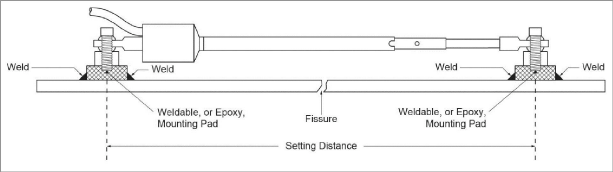
Figure 4: Installation using Weldable Fixtures
Installation instructions:
1.Determine the proper setting distance using the spacings listed in Figure 1.
2.Grind, sand, or otherwise prepare the surface of the steel around the area of each weldable fixture.
3.Position the welding fixtures on prepared surfaces.
4.Verify the placement again, then tack weld to the member.
5.Remove the PVC slotted sleeve or dowel pin securing the transducer shaft.
6.Thread the cap screw through the swivel bearing and through the half-inch spacer on each end.
7.Tighten the cap screws into the welding fixtures as depicted in Figure 4.
8.Check and record the reading with a portable readout. Use Table 2 or the readings on the calibration sheet to check the position.
2.2.3Installation using Groutable Anchors
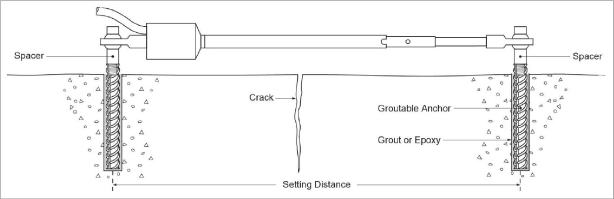
Figure 5: Installation using Groutable Anchors
Installation instructions:
1.Determine the proper setting distance using the spacings listed in Table 1.
2.Using a hammer drill (or other suitable equipment), drill two half-inch diameter holes approximately three inches deep at the proper locations. Shorter holes may be drilled if the anchors are cut down accordingly.
3.Push the cap screws through the swivel bearings and spacers on each end of the crackmeter and then loosely thread them into the groutable anchors.
4.For midrange position installations, secure the transducer shaft in place by leaving the PVC slotted sleeve or dowel pin installed.
5.Fill the holes three quarters full with grout or epoxy. For holes drilled overhead use a quick setting grout or epoxy.
6.Push and twist the anchors in until the tops are flush with the surface. Wipe any excess epoxy clear of the tops of the anchors.
7.After the grout or epoxy has set, install and tighten the set screws.
8.Remove the PVC slotted sleeve or dowel pin if it was not removed earlier.
9.Check and record the reading with a portable readout. Use Table 2 to check and adjust the position as needed.
2.2.4Installation using Expansion Anchors
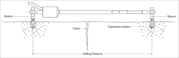
Figure 6: Installation using Expansion Anchors
Installation instructions:
1.Determine the proper setting distance using the spacings listed in Table 1.
2.Using a masonry drill (or other suitable equipment), drill two 10 mm (3/8") diameter holes, 32 mm (1.25") deep at the proper locations.
3.Insert the expansion anchors into the holes, with the slotted end down.
4.Insert the setting tool into the anchor, small end first. Expand the anchor by hitting the large end of the setting tool with several sharp hammer blows.
5.Remove the PVC slotted sleeve or dowel pin securing the transducer shaft.
6.Push the cap screws through the swivel bearings and spacers on each end of the crackmeter and then tighten the cap screws into the anchors.
7.Check and record the reading with a portable readout. Use Table 2 to check and adjust the position as needed.
Regarding Models 4420-1-3 mm (.125"), 4420-1-12.5 mm (.5"), and 4420-1-25 mm (1"), please keep the following in mind:
■If the reading is not in the proper range after installation, make adjustments using the threaded extension at the end of the transducer shaft.
■To make accurate adjustments, attach the transducer to the anchor at the cable end, and temporarily remove it from the opposite anchor.
To make an adjustment, do the following:
1.Loosen the locking nut and then rotate the threaded rod into or out of the end of the transducer shaft.
Note: Grip the transducer shaft while rotating the threaded rod. Never rotate the transducer shaft beyond 180 degrees, or gauge failure may result.
2.After making an adjustment, align the hole in the swivel bearing over the anchor and check the reading.
3.Make adjustments until the desired reading displays on the readout.
4.Push the cap screw through the swivel bearing and spacer.
5.Tighten into the anchor.
6.Re-tighten the locking nut.