 Loading... Please wait...
-
Products
- Piezometers
- Inclinometers
- Strain Gauges
- Data Loggers
- Time Domain Reflectometry (TDR)
- Displacement Transducers
- Extensometers
- Settlement Sensors
- Pressure Cells
- Load Cells
- Tiltmeters · Pendulums
- Readouts
- Visualization Software
- Stressmeters
- Distributed Fiber Optic Sensors
- Temperature
- Instrumentation Cables
- DeAerators
- Vibration Monitoring
- Custom Instrumentation
- Discontinued
- Support
- Training
- Contact Us
- News
- Company
- Projects
- Resources
- Videos
- Links
Projects
Pipelines
-
Overview
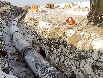
Where pipelines pass over unstable slopes any movements may result in lateral forces to act on the pipe which may cause it to bend and possibly rupture. To monitor the strains in the pipe that may develop under these conditions vibrating wire strain gauges can be attached various points along the pipe, at 120 degree spacings, such that the magnitude and direction of the resultant tensile and compressive strains can be determined. The strain gauges can be connected to multiplexers (hard wired or wireless) which in turn are connected to data acquisition systems for near real time monitoring and for data visualization over the internet.
The unstable slopes themselves can also be monitored using inclinometers (to identify the location of any slip planes) and piezometers to monitor any changes in pore pressure—increases of which often forewarn any slope instability. (Weather stations should also be considered to determine if any movements and/or increases in pore pressure can be correlated with periods of heavy or steady rainfall). For surficial movements along the slope, extensometers, with extended range capability, can be installed at strategic locations. (As with the strain gauges, the inclinometers, piezometers, extensometers and weather stations can all be connected to data acquisition systems for on line monitoring).
Case Histories
-


Gas Pipeline
West Virginia, USA
At a site in West Virginia, a gas pipeline passes through a section of ground that exhibits instability and some minor sliding, which may adversely affect the operation of the pipeline.
In order to assess the effects of potential ground movements, two locations along the pipeline were instrumented with three Model 4150 Spot Weldable Vibrating Wire Strain Gauges. Each location has a group of strain gauges attached to the pipe at the 9 o’clock, 12 o’clock and 3 o’clock positions to determine the magnitude and direction of any resultant tensile and compressive strains.
The gauges were spot welded to the bare pipe after the protective covering was removed. The instrumented section was covered with a waterproofing material, and then wrapped with special tapes to further prevent moisture ingress that might cause corrosion of the pipeline.
The cables from each gauge were routed to a 16-channel datalogger, located above the pipeline, which was configured to read the gauges on a daily basis.
Share your Project!
GEOKON would like to share customer projects and success stories with the visitors of our website. If you would like your project summary to be featured on our Recent Projects page, added to our collection of various Projects and promoted on social media, please complete and submit your project for review and consideration. As a token of our appreciation, GEOKON will send you a small gift for your contribution!
