 Loading... Please wait...
-
Products
- Piezometers
- Inclinometers
- Strain Gauges
- Data Loggers
- Time Domain Reflectometry (TDR)
- Displacement Transducers
- Extensometers
- Settlement Sensors
- Pressure Cells
- Load Cells
- Tiltmeters · Pendulums
- Readouts
- Visualization Software
- Stressmeters
- Distributed Fiber Optic Sensors
- Temperature
- Instrumentation Cables
- DeAerators
- Vibration Monitoring
- Custom Instrumentation
- Discontinued
- Support
- Training
- Contact Us
- News
- Company
- Projects
- Resources
- Videos
- Links
Projects
Wind Turbines
-
Overview
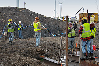
Newly constructed wind turbines often require instrumentation to verify the design and long-term performance of their foundations. For piled foundations, sister bars, strain gauges and incremental extensometers are often used to measure load distribution along the pile, and in-place inclinometers (installation shown at left) are used to measure deflections during any pile testing programs undertaken to efficiently design the pile dimensions. The same sensors can be used to monitor loads in the piles, in near real-time, and load cells can be employed to monitor the effectiveness of any lock off bolts. For raft foundations, tiltmeters, earth pressure cells, deformation gauges, differential settlement systems and multiple position borehole extensometers can be installed to detect tilting and to monitor any separation or movement between the foundation and the underlying soil/rock material. Biaxial tiltmeters, strain gauges, and dynamic strain transducers are useful to measure any tilting and distortions of the tower. Dataloggers are used to gather and transmit information and data, via the internet, to provide near real-time data display and monitoring at any location using Vista Data Vision software.
Case Histories
-


Moray East Offshore Wind Farm
Outer Moray Firth, Scotland
The Moray Offshore Wind East Limited (MOWEL) Wind Farm is located on the Smith Bank in the outer Moray Firth. It lies 12 nautical miles (about 22 km) from the Caithness Coast and covers an area of 520 km². A total of 100 wind turbine generators (WTG) of type MHI Vestas V164-9.5MW are planned to be installed. The hub height of the turbines varies between 113.44 and 116.93 mLAT and the interface between tower bottom and the top of the foundation vary between 23.4 and 26.9 mLAT. The nominal water depths at the site vary between -39.2 and -53.3 mLAT.
The foundation concept at the MOWEL Wind Farm is a jacket structure with three legs supported by pre-installed driven piles. The jacket substructure and the piles are connected through a grouted connection. A transition piece (TP) of box girder type connects the jacket legs to the tower (Ramboll GmbH, 2019).
Critical failure mechanisms, from root cause to failure modes, ultimately defines the parameters to be measured. The critical failure modes for main system components like primary steelwork, secondary steelwork and corrosion protection system were identified as:
- Permanent Deformation
- Cracks
- Early consumption of fatigue life
- Tilting
- Excessive Vibration
Specifically, the failure of the following has been targeted for monitoring:
- Fatigue Crack of the Jacket Lattice Structure: Excessive loads can accumulate due to a number of reasons, amongst them the development of scour, corrosion due to flaws in coating or flaws in weld due to poor manufacture.
- Tilting or Deformation of the Jacket Lattice Structure: Unexpected movement can occur due to excessive scour, particularly during extreme conditions (storm events).
- Behaviour out of WTG specification of the Jacket Lattice Structure: Natural frequency of the structure will vary depending on ground conditions (which can be heterogeneous).
- Fatigue Crack of the Piles can develop as a result of scour hole development in combination with microbiologically induced corrosion.
- Fatigue Crack of the Transition Piece: Underestimation of the WTG loads in the design of the TP could lead to this being substandard, and developing cracks over time.
Instrumentation used: Model 6161 MEMS Tilt Sensors
The purpose of the GEOKON Instrumentation is to monitor the tilt or pivot of the transition piece on 4 offshore wind turbine generators. The data from the sensors will be used for fatigue analysis.
Project submitted courtesy of James Fisher Testing Services, United Kingdom.
-


Rock Anchored Wind Turbine Foundation
New Hampshire, USA
An extensive monitoring program comprising a series of vibrating wire load cells and automatic data acquisition systems has been deployed on a number of wind turbine foundations to measure tie-down anchor loads.
Site photographs:
- Top left: 4 Load Cells installed (at 90°) on the rock anchored wind turbine foundation.
- Bottom left: Load cell installed on a 3" anchor, ready for tensioning.
- Bottom right: Temporary stack of steel plates to allow use of an unmodified tensioning jack.
Photographs courtesy of Cianbro Corporation, Maine, USA.
Share your Project!
GEOKON would like to share customer projects and success stories with the visitors of our website. If you would like your project summary to be featured on our Recent Projects page, added to our collection of various Projects and promoted on social media, please complete and submit your project for review and consideration. As a token of our appreciation, GEOKON will send you a small gift for your contribution!
