 Loading... Please wait...
-
Products
- Piezometers
- Inclinometers
- Strain Gauges
- Data Loggers
- Time Domain Reflectometry (TDR)
- Displacement Transducers
- Extensometers
- Settlement Sensors
- Pressure Cells
- Load Cells
- Tiltmeters · Pendulums
- Readouts
- Visualization Software
- Stressmeters
- Distributed Fiber Optic Sensors
- Temperature
- Instrumentation Cables
- DeAerators
- Vibration Monitoring
- Custom Instrumentation
- Discontinued
- Support
- Training
- Contact Us
- News
- Company
- Projects
- Resources
- Videos
- Links
Resources
Session 05
Load Cell Data Interpretation

Posted April 08, 2022
A question that often surfaces when using load cells is why the load cell readings and applied pressure gauge readings do not match.
At times, the difference between the hydraulic jack pressure and calculated loads from the cell could be upwards of 15% or more. How this discrepancy is resolved, minimized, or accepted depends on the type of load cell, the configuration, the loading process, and the project's acceptance criteria.
Load cells are devices used in-line between a structure or element and the applied forces (or another structural element) to provide an indication of what the applied forces are. Over the years, loads cells have ranged from mechanical to hydraulic to the more commonly used electrical resistance and vibrating wire types. This discussion focuses primarily on electrical resistance and vibrating wire load cells; however, the principles discussed can also be applied to other types of load cells.

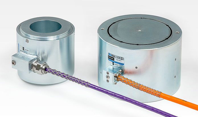
Model 3000 Electrical Resistance Load Cell (left) and Model 4900 Vibrating Wire Load Cell (right).
Field Calibration
The load cells from GEOKON are calibrated through at least two loading cycles, with a few initial loading cycles applied to "break-in" the cell prior to calibration. The calibrations are performed using custom compression testing machines that are calibrated annually and have accuracies traceable to the National Institute of Standards and Technology (NIST). Because field conditions rarely mimic those of the laboratory or calibration facilities, it is recommended that the user have their hydraulic jack calibrated in conjunction with the load cell if possible. Ideally, the field and calibration configurations should be identical.
Bearing Plate Design
Load cells are intended to be used in conjunction with specially machined bearing plates that help distribute applied forces evenly to the load cell. Typically, these bearing plates are heat-treated and machined with parallel bearing surfaces. Bearing plates should be big enough to cover the surface area of both the load cell and the pressure jack. The thickness of the plates is dependent upon the load. The following can be used as a general rule of thumb:
- 100-200 kip load: 25 mm (1") thick
- Up to 400 kip load: 37 mm (1.5") thick
- Up to 1,000 kip load: 50 mm (2") thick
- Up to 2,000 kip load: 75 mm (3") thick
The use of spherical bearing plates can improve loading conditions and reduce potential eccentric loading on the cells; however, the spherical plate components should have matching concave/convex surfaces and be paired together on either the top or bottom of the load cell, with a minimum total thickness (of the paired plates) as indicated above.
The diameter of the hydraulic jack loading surface should be similar to that of the load cell bearing surface. A smaller jack can result in over-registering the measuring load, while a larger jack can result in under-registering.

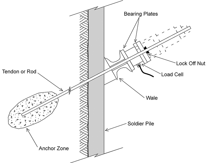
A load cell used on a tieback for the permanent monitoring of loads.
Friction Between the Bearing Plate and the Load Cell
Friction between the bearing plate and the load cell can radically affect the cell's performance. Interposing deformable plates or lubricant between the bearing plates and the load cell in the field will cause the load cell to over-register, perhaps by as much as 10%. For best results, it is important to calibrate the load cell in the laboratory under the same loading conditions as will be used in the field. End effects of this nature can be reduced somewhat by using tall load cells. A rough rule of thumb for good load cell design calls for a load cell height of at least four times the wall thickness of the loaded annulus. On jobs where space restrictions require a pancake-style load cell, friction between the bearing plates and the load cell can give rise to large hysteresis effects between loading and unloading cycles.
Eccentric Loading
Another factor that can influence the performance of load cells and their output is the testing setup. To reduce potential eccentric loading in vertical applications such as load testing or tie-downs, it is important to use appropriately sized components that are stacked concentrically. With inclined applications, like tieback or soil anchor testing/loading, the alignment of the components is not as easy. Gravity will influence the position of the components until enough force is applied to fix the pieces in place; however, by that time, the bearing plates or the load cell may have shifted slightly from the center alignment. Eccentric loading will occur on the load cell if the components are out of alignment. Electrical resistance and vibrating wire type load cells are constructed of several strain gauges mounted around the perimeter of the body of the cell. Some eccentricity can be accounted for and dealt with by this configuration, but frequently some portion of it remains.
Temperature Effects
Temperature compensation is achieved using strain gauges whose thermal coefficient is the same as the load cell material. Typically, the temperature coefficient of the load cell is insignificant; however, if there are significant temperature swings during the process of testing the load cell, there could be thermal influences on the data output. The thermal coefficient of GEOKON load cells can be measured at the factory if required. For vibrating wire type load cells, a decrease of approximately 1 Digit per degree Celsius increase can develop. For resistance type load cells, the temperature effect is about 0.02 percent of the full-scale range per degree Celsius change.
Zero Reading
Establishing a valid zero reading before performing the test or installing the load cell is critical to getting good results. Zero readings should be obtained on-site, preferably with the load cell on its side so that no applied load (even of the cell itself) is affecting the zero reading. Rotate the cell to different points of contact while on its side to obtain three different readings. The average of these three readings is the zero reading against which all subsequent readings will be compared.
